
Manual


17
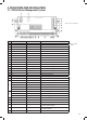
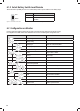
No. LED COLOUR STATUS DESCRIPTION
1 Mains GREEN
ON AC input OK
OFF AC disconnected
4XLFNöDVKLQJöDVKWZLFHHYHU\VHFRQG AC input abnormal
2
Starter
Battery
GREEN
ON Alternator charging the SERVICE battery
6ORZöDVKLQJöDVKRQFHHYHU\VHFRQG Starter battery is >13.4V and is being charged by
the PM435
4XLFNöDVKLQJöDVKWZLFHHYHU\VHFRQG The Starter Battery is 2~13.4V or >16.0V, while
AC power is connected.
OFF Starter battery is disconnected.
3
PV
6RODU
GREEN
ON Solar charging the battery
6ORZöDVKLQJöDVKRQFHHYHU\VHFRQG The input voltage of the Solar is normal and the
service battery is charged by the AC or Alternator
4XLFNöDVKLQJöDVKWZLFHHYHU\VHFRQG PV input error
OFF PV disconnected
4 &+* GREEN
ON Battery charged
)ODVKLQJöDVKRQFHHYHU\VHFRQG Battery charging
6ORZöDVKLQJVHFRQGRQVHFRQGVRII Battery discharge
OFF Battery disconnected
5 FAULT RED
ON Short circuit
Flash once per cycle Service battery voltage low
Flash twice per cycle Service battery voltage high
Flash 3 times per cycle PM435 unit Over Temperature
Flash 4 times per cycle %XONFKDUJHWLPHRXW
Flash 5 times per cycle VCR anomaly
Flash 6 times per cycle Environment Over Temperature
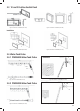
5.3 Monitor PMLCD-BT
5.2 10 Position Switch Panel PM4SW10
5.2.1 2 Position Switch Panel PM4SW2
Time
Figure 28 An overview of PM4SW10
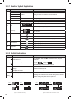
No. NAME TYPE DESCRIPTION
1 Ceiling light
DC load control
Load control, support
brightness adjustment
2 Bedroom light
3 Dinning light
4 Outside light Load control, on/off control
5 Night mode Scene mode Refer to Chapter 2.11
6 Water pump
DC load control
Load control, on/off control
7 TV
8 Switch A
9 Switch B
10 Load Refer to Chapter 1.3
1 2 3 4 5
6 7 8 9 10
Table 10 Button explanation of PM4SW10
No. NAME TYPE DESCRIPTION
1 Bedroom light DC load control Load control, brightness
adjustment
2 Night light Scene mode Load control, Brightness
adjustment, refer to Chapter
2.11
P3 P4 ADDRESS
On On 1#
On Off 2#
Off On 3#
Off Off 4#
Figure 29 An overview of PM4SW2 Table 11 Button explanation of PM4SW2
1 2
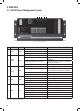
Figure 30 An overview of Monitor PMLCD-BT
TBA
Outdoor temperature
Output power
Charging state
Service battery: Type/Capacity
Service battery: Voltage/Current/Time to go
Service battery SOC (State of Charge)
Voltage of vehicle battery
VCR connection
Light/Enter/Setting switch
Load/Down switch
Date
Water tank 1
Water tank 2
Water tank 3
Water tank 4
Power Source
Solar charge
Water pump 1/2
Alarm error code
Silent/Esc switch
Pump/Up switch
Table 12 Switch address settings of PM4SW2
When there are more than one
PM4SW2 in the system. The customer
should pay attention to the address
setting by dip switch P3 and P4 for
them. They should not be the same.