SMART AUTOMATIC 12/24 VOLT SOLAR CONTROLLER 4 STAGE CHARGING P/No.
IMPORTANT SAFETY INFORMATION Please read this instruction thoroughly before installing the product. WARNINGS • This charger is designed for indoor use only • Do not disassemble the controller. Take to a qualified person if the unit requires repairing • Lead acid batteries can be dangerous. Ensure no sparks or flames are present when working near batteries • Eye protection should always be used.
FEATURES • 4 Stage charging ensures the battery is charged to the optimum level (Bulk, Absorption, Equalisation and Float) • Advanced MCU control pulse width modulated (PWM) technology, high efficiency operation • Programmable for Gel, AGM and Conventional lead-acid (WET) Batteries • Built in regulator to prevent your battery from being overcharged. Overcharging occurs when the charge voltage is unregulated.
WIRING CONNECTIONS 1. Connect components to the charge controller in the sequence as shown above and pay particular attention to the “+” and “-”. Please don’t insert the fuse or turn on the breaker during the installation. When disconnecting the system, the order will be reversed. 2. Power on the controller, check the LCD screen turns on. If the screen does not power up, refer to page 9 TROUBLESHOOTING. Always connect the battery first, in order to allow the controller to recognize the system voltage. 3.
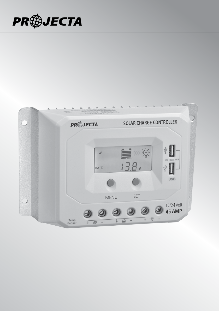
OPERATION Button Function Button Function MENU Button • Browse interface • Setting parameter SET Button • Load ON/OFF • Clear error • Enter into Set Mode • Save data LCD Display Status Display Item Icon Status Day Night PV Array No Charging Charging PV Voltage, Current, Power Battery capacity, in charging Battery Battery voltage, current, temperature Battery type Load ON Load Load OFF Load voltage, current, load mode 5
BROWSE INTERFACE NOTE 1. When no operation, the interface will automatically cycle, but the following two interfaces will not display. 2. Accumulative power zero clearing: Under PV power interface, press SET button and hold on 5s then the value blink, press SET button again to clear the value. 3. Setting temperature unit: Under battery temperature interface, press SET button and hold on 5s to switch to Fahrenheit or Celsius.
LOAD MODE SETTING Operating Steps Under load mode setting interface, press SET button and hold on for 5 seconds until the number begins flashing, then press MENU button to set the parameter, press SET button to confirm.
PROTECTION Protection Conditions Status PV Reverse Polarity When the battery is correct connecting, the PV can be reversed. The controller is not damaged Battery Reverse Polarity When the PV is not connecting, the battery can be reversed.
TROUBLESHOOTING Faults Possible reasons Troubleshooting The LCD is off during PV array disconnection daytime when sunshine falls on PV modules properly Confirm that PV wire connections are correct and tight Wire connection is correct, LCD not display 1) Battery voltage is lower than 9V 1) Please check the voltage of battery.
SPECIFICATIONS Item Nominal system voltage Battery input voltage range Rated charge/discharge current SC220 SC245 SC260 12/24VDC 12/24VDC 12/24VDC 9V–32V 9V–32V 9V–32V 20A@55OC 45A@55OC 60A@55OC 50V 50V 50V Max. PV open circuit voltage Battery type Sealed(Default)/Gel/Flooded Bulk/Absorption Charging Voltage Sealed:14.4V/ Gel:14.2V/ Flooded 14.6V Equalize Charging Voltage Sealed:14.6V/ Gel: No/ Flooded 14.8V Float Charging Voltage Sealed/Gel/Flooded:13.