USER GUIDE ENGLISH Downloaded From projector-manual.
A english TABLE OF CONTENTS A Table of contents 03 B Introduction 04 C Safety & Warnings 04 D Supplied material 07 E Optional lenses 08 F Overview 09 G Keypad 10 H Indicators 11 I Remote control 12 J Connector panel 14 K Set up 15 L Image adjustments 16 M Lamp operation 17 N Pin Code 17 O Ceiling mount 18 P Using the projector 20 Q Menu system 21 R RS 232 and LAN control 29 S Trouble shooting 29 T Maintenance 30 U Service information 30 V Lam
C INTRODUCTION SAFETY & WARNINGS english english B This digital projector is designed with the latest state-of-the-art technologies in illumination, imaging, optics, electronics, thermal and industrial design in order to serve traditional as well as novel imaging applications across a variety of markets, offering features such as: - PROFESSIONAL GRADE POWERED PROJECTION LENSES with bayonet mounts - DUAL LAMP SYSTEM with separate lamps for improved life, redundancy and 24/7 operation - DUAL OPTOMECHANIC
english english SAFETY & WARNINGS SAFETY & WARNINGS Do not operate the projector outside its temperature and humidity specifications, as this may result in overheating and malfunctioning. Only connect the projector to signal sources and voltages as described in the technical specification. Connecting to unspecified signal sources or voltages may lead to malfunction and permanent damage of the unit. Allow the unit to cool down for 60 minutes before lamp change.
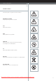
english SAFETY & WARNINGS WARNING SYMBOLS READ USER GUIDE Attention! Read the user guide for further information! DANGEROUS VOLTAGE Danger! High voltage inside the product! HOT Warning! Hot surfaces! WAIT Warning! Wait until cooled down! MERCURY Warning! Product contains mercury! Recycle properly, do not dispose of in ordinary waste! UV Warning! UV radiation inside the product! RECYCLE Warning! Recycle properly, do not dispose of in ordinary waste! NO TELEPHONE Warning! Do not connect to telephone
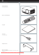
D english SUPPLIED MATERIAL Projector without lens Lens supplied seperately Remote control with batteries User guide Power Cord (country dependent) Ceiling mount cover Before Set up and Use Unpack the supplied parts and familiarise yourself with the various components. Downloaded From projector-manual.
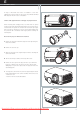
E english OPTIONAL LENSES A range of fixed and zoom lenses is available to cover most applications, both front and rear. The lenses are powered and fitted with a bayonet mount for ease of installation. A Switch off all equipment before setting-up for proper function. When mounting and changing lenses, be aware that the optical system is exposed to dust and foreign particles as long as the lens is not attached to the system. Do not leave the lens mount open longer than necessary to change lens.
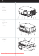
F english OVERVIEW A Lens B IR sensor C Ventilation D Lens release E Power connector B C B F Keypad G Connector panel H LCD I Lamp lids A C D C E F B H G J Adjustable feet K Security lock L Ceiling mount J L C B J I K B Downloaded From projector-manual.
G english english KEYPAD The keypad is illuminated for operation in dark environments. Available functions are illuminated in yellow while selected (active) functions are illuminated in green. Functions that are not available are not illuminated. In addition to the various functions, 10 keys are numbered 0-9. These keys are used for PIN code and other numeric functions as applicable. SHUTTER Press SHUTTER to stop the projected image completely. VGA Selects the VGA input as active source.
H english INDICATORS STATUS Indicates the overall system status by green, yellow and red colors. PERMANENT GREEN LIGHT The projector is turned on and in normal operation. PERMANENT YELLOW LIGHT The unit is in standby mode; no source(s) connected, or the source(s) connected are inactive or switched off, thereby activating the powersave function (DPMS). You may enable or disable the power save function in the SET UP sub menu, DPMS on or off. FLASHING YELLOW LIGHT Please wait.
I english REMOTE CONTROL The remote control allows flexible access to the projector settings, either through direct keys, or through the menu system. The remote control is backlit for use in dark environments. It also has a datajack that allows for wired connection to the projector. When the wire is connected, the IR (infra-red) beam and internal batteries are switched off. The remote control can be operated either in 'broadcast mode', or 'individual mode'.
english REMOTE CONTROL X-PORT 1, 2 Activates the X-PORT 1, 2. These keys are enabled by the X-PORT 1, 2 devices as and when attached. Functionality depends on the actual devices connected SHUTTER Toggles the mechanical shutter on and off. ZOOM Press the ZOOM keys to zoom the image in and out. FOCUS Press the FOCUS keys to focus the image. SHIFT Press SHIFT, then the arrow keys to shift the image up, down or sideways.
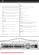
J english CONNECTOR PANEL english CONNECTOR PANEL The conector panel may be illuminated by pushing the LIGHT key on the keypad. A C-VIDEO: Used for standard video quality. H RS 232 control in-out: Allows for wired remote control and monitoring of many projector functions used in installation environments. The secondary output connector allows for daisy-chaining, enabling both individual and global control and monitoring of multiple projectors. B S-VIDEO: Used for improved quality video.
K english SET UP SET UP VIDEO Before setting-up, switch off all equipment. Four video sources may be connected, using the YPbPr (component), BNC (RGB), S-VIDEO (super video) and VIDEO (composite video) inputs. Component and RGB video will display more detailed images. Composite video yields images with less detail. In addition, the DVI-D input can be used with video sources (DVD player fitted with an HDCPTM compliant DVI or HDMI connector) for a pure digital connection. Connect the power cord.
L english IMAGE ADJUSTMENTS Various optical adjustments are available, depending on your choice of lens. All lens adjustments are motorized and controlled by the keypad, remote control or by RS232 or LAN. Two kinds of lenses are available; fixed or zoom. A fixed lens has permanent focal length, or throw ratio. A zoom lens has variable focal length or throw ratio. In addition, fixed lenses may or may not be shiftable, depending on type and model. See the specifications for the particular lens.
N LAMP OPERATION PIN CODE english english M The projector is fitted with two individual projection lamps that can be run in various modes. In addition, lamps can be replaced as needed separately. This ensures an optimized cost of ownership. Individual lamp timers are maintained for each lamp. The projector may be controlled by a PIN (Personal Identity Number) code. The PIN code is 4 digits, and if the PIN code is activated, you must issue the right code to unlock the projector.
O english CEILING MOUNT The projector can be ceiling mounted using an approved UL tested/ listed ceiling mount fixture, with a capacity of minimum 60 kg / 130 lbs. 95 82,5 59,5 53 For ceiling mount use M6 screws that penetrate maximum 15 mm / 0.6” into the projector body. 15,5 94,3 111,8 384,9 For proper ventilation the minimum distance from ceiling/ rear wall should be: 30/ 50 cm, 12/ 20 inch. Ceiling Mount Interface M6 Threads 163,3 300mm 123,1 500mm Downloaded From projector-manual.
english CEILING MOUNT CEILING MOUNT COVER The auxiliary cable cover can be mounted on the projector to conceal the interface cables and power cord when the unit is ceiling mounted. Connect all cables and fix them in place before the cable cover is attached to the projector. A Attach the cable cover to the projector by inserting the horisontal hooks on the cover in the horisontal slots on the rear of the projector.
P english USING THE PROJECTOR After setting-up, switch on all equipment. The projector can be controlled by the keypad on the rear, by the remote control or using the RS232 or LAN interfaces. When using the remote control, either all or select individual units may be addressed, see the CONTROL sub menu - RC ID. By activating the RC ID, individual control of units in a multiple-unit set-up is then made possible. To switch the projector on, firmly press the POWER button on the keypad or the remote control.
Q english MENU SYSTEM The menu system gives access to a multitude of image and system controls. The menu system is structured through a top menu and several sub menus. The sub menus may vary depending on the actual source selected. Some functions are not available with some sources. When accessing the menu system, you will enter at the position you left last time you were using the menu system.
english MENU SYSTEM PICTURE SUB MENU S-VIDEO / C-VIDEO brightness Adjusts the image brightness. A higher setting will increase the brightness, a lower setting will decrease the brightness of the image. contrast Controls the contrast of the image. A higher setting will yield a 'harder' image with larger difference between shades, while a low setting will produce a 'softer' image with less difference between shades. color Adjusts the color saturation.
english MENU SYSTEM DYNAMIC SUB MENU S-VIDEO / C-VIDEO white boost Increases the white level of the image for enhanced contrast white boost gamma The source image is adapted to characteristics typical to certain applications. This enables an optimized display of images, depending on whether the source is video, computer etc. digital noise reduction DVI setup Enables an expanded dynamic range when using DVI.
english MENU ADJUSTMENT ADVANCED SUB MENU S-VIDEO / C-VIDEO h position Shifts the image sideways. H position 50 V position 50 v position Shifts the image up and down. color temp 6500 7300 9300 custom custom color phase Adjust for stable image. A jittery image may appear with certain VGA sources. You may also press the AUTO button on the keypad or remote control to optimize. frequency Adjust image width.
english MENU SYSTEM SET UP SUB MENU keystone V Adjust vertical keystone correction. Compensates for the geometrical distortion of the projected image resulting from tilting the projector to shoot higher up on the wall. keystone H Adjust horizontal keystone correction. Compensates for the geometrical distortion of the projected image resulting from shooting the image at an angle sideways to the screen.
english MENU SYSTEM UTILITIES SUB MENU FOR ALL system information Displays information about the source and projector status. system information OSD on off OSD Turn the On Screen Display on (display) or off (hide) during source scan. OSD timeout 50 seconds OSD timeout Defines how long OSD is displayed after last key action before it disappears from the screen. OSD background Select background mode, whether transparent or opaque. reset Resets the projector to its basic settings.
english MENU SYSTEM CONTROL SUB MENU FOR ALL mode Selects between RS232 and X-PORT control modes. mode RS232 address For use when daisy-chaining several units. Select auto or fixed address. Only one address scheme is allowed per daisy-chain. The auto address is allocated following the relative position in the daisychain. The fixed address is an absolute address. Only unique fixed addresses are allowed.
english MENU SYSTEM LAMP SUB MENU FOR ALL Mode select dual or single lamp mode. mode eco select eco mode (reduced power for longer lamp life). advanced eco dual on single off press ADVANCED FOR ALL advanced individual lamp control. single lamp1 lamp 2 lamp1 power 100 single select lamp 1 or lamp 2 as active lamp. lamp 1, lamp 2 power select lamp power from 80-100%.
S RS 232 AND LAN CONTROL TROUBLE SHOOTING english english R RS 232 NO IMAGE You may control and monitor the projector remotely through the serial RS232 control interface. No connection: Check if all connections are properly made. Source off: Check if the equipment is powered on. Two RS232 protocols are employed. A simple instruction set (SIS) ASCII protocol gives access to the most frequently used commands.
U MAINTENANCE SERVICE INFORMATION The projector may from time to time need cleaning. Never open the unit, as this will void any warranties. Refer service and repair to qualified personnel only. The projector is using lamps that have a limited life time. Please refer to the LAMP CHANGE section below for further details. Only the exterior of the unit may be cleaned. Use a damp cloth.
V english LAMP CHANGE The LAMP indicators on the keypad will turn red when lamp life expires. Change the lamp when lifetime expires. Always replace lamp with the same type and rating. The lamp includes an electronic lamp timer that is tracking the life time of the lamp. A Always disconnect the power cord and wait until the projector has cooled down (60 minutes) before opening the lamp cover . A Release the screw (LAMP 1) or (LAMP 2) depending on which lamp that needs to be replaced.
W english english TECHNICAL DATA PROJECTOR UNIT Resolution 1400 x 1050 (native) SXGA+, 4 : 3 aspect ratio Display technology Single chip DLP™ technology by Texas Instruments® Display device LVDS DMD™ with DarkChip3™ technology Computer Compatibility UXGA, SXGA+, SXGA, XGA, SVGA, VGA, PC, MAC, SGI and other workstations, RGBHV, RGBS, RGsB Video Compatibility HDTV (1080i, 720p, 576i/p, 480i/p), NTSC, NTSC 4.43, PAL, PAL-M, PAL-N, SECAM.
english english TECHNICAL DATA PROJECTOR UNIT Temperature operating 0-40°C / 32-104°F, 0-1500 m / 0-4950 ft 0-35°C / 32-95°F, 1500-3000 m / 4950-9900 ft Temperature storage -20 - 60°C / -4 - 140°F Humidity operating 20-90% RH, non-condensing Humidity storage 10-95% RH, non-condensing LENSES Short fixed lens f = 15.32 mm F = 2.1 - 6.5 throw ratio = 0.8 : 1 (distance : width) throw distance = 0.5 - 2.5 m / 1.65 - 8,25 ft.
english TECHNICAL DATA CONNECTORS S-Video G/Y Computer DVI Computer VGA 1 BNC H - C BNC V RS-232 in RC in LAN 4 PIN MINI DIN PHONO/RCA DVI-D 15 HIGH DENSITY BNC MALE BNC MALE 9 PIN DSUB 3,5mm stereo 1 TX+ FEMALE FEMALE FEMALE mini jack 2 TX- 3 RX+ DSUB FEMALE 1 GND STEM GREEN: G/Y 1 TMDS Data 2- 1 Analog R in STEM: STEM: Vertical 1 NC TIP: 5V DC 4 GND 2 GND SHIELD: GND 2 TMDS Data 2+ 2 Analog G in Horizontal/ sync.
english TECHNICAL DATA THROW RATIOS F3, ZOOM AND FIXED LENSES Image width Image height Screen diagonal ft m ft m ft 9.00 29.70 12.00 39.6 15.00 49.50 8.25 27.23 11.00 36.3 13.75 65.18 7.50 24.75 10.00 33.00 12.50 41.25 6.75 22.28 9.00 29.70 11.25 37.13 6.00 19.80 8.00 26.40 10.00 33.00 5.25 17.33 7.00 23.10 8,75 28.88 4.50 14.85 6.00 19.80 7.50 24.75 3.75 12.38 5.00 16.50 6.25 20.63 4.00 13.20 5.00 16.50 3.00 9.90 3.75 12.38 2.00 6.60 2.
X FCC This equipment has been tested and found to comply with the limits for a Class A digital device, pursuant to part 15 of the FCC Rules. These limits are designed to provide reasonable protection against harmful interference when the equipment is operated in a commercial environment. This equipment generates, uses, and can radiate radio frequency energy and, if not installed and used in accordance with the instruction manual, may cause harmful interference to radio communications.
USER GUIDE ENGLISH Downloaded From projector-manual.com Projectiondesign Manuals *601.0068.