
Manual


6
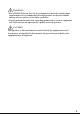
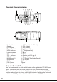
Physical Characteristics
Headset Jack LNR (Last Number Redial)
Speaker DEL (Delete)
LCD Display RCL (Recall)
Test mode switch Volume adj.
ADSL indicator Brightness adj.
CABLE indicator Up
TEL + indicator Down
TEL – indicator Number pad 0~9, , #
STO (Store) Strap hole
M1 (Memory 1) T-P Switch (Tone/Pulse Switch)
On/Off hook RJ-45 Jack
OUT Microphone
PSE (Pause) Figure 1
Test mode switch
The Test mode switch is a slide switch located on the right side of MT-8002 (see
Figure 1). Switching the Test mode switch to the TEL position make the test
set acts as a telephone line tester. Switching the Test mode switch to the ADSL
position make the test set acts as a LAN signal detector. Switching the Test mode
switch to the CABLE position will let the test set acts as a CABLE tester.
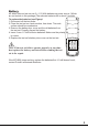
1
AAA
AAA
AAA
2
3
4
5
6
7
8
10
15
13
1221
17
18 19
16
9
14
1120
2223
24
25
25
24
23
22
21
20
19
18
17
16
15
14
12
11
10
9
8
7
6
5
4
3
2
1
13