$15.
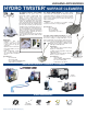
XBTIJOH!BDDFTTPSJFT HYDRO TWISTER ® The ANT3C Contractor Series HYDRO TWISTERS are the proven choice for professional surface cleaning with three options for your cleaning needs. The ANT3C is a 3-in-1 rotary surface cleaner and includes a spot / gum remover and a hydro broom creating an all-in-one portable system. The dual trigger gun control allows you to activate either device simply by pulling the appropriate trigger.
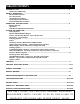
TABLE OF CONTENTS 3 INTRODUCTION ............................................................................................................................... 4 Statement of Warranty SAFETY WARNINGS ....................................................................................................................... 5 Electrical Precautions Fire Precautions Ventilation Precautions Spray Injection Precautions Personal Hazard Precautions OPERATING INSTRUCTIONS ............................................
INTRODUCTION: THANK YOU: The employees and management of HYDRO TEK SYSTEMS, INC. thank you for selecting our products. The production and quality assurance personnel have taken the greatest care in the assembly process to ensure that your new Industrial Cleaning Equipment exceeds the standards set by you, the customer, by Hydro Tek engineering and management, and by our safety certification to U.L. 1776. YOUR RESPONSIBILITY: This operator’s manual was compiled for your benefit.
IMPORTANT SAFETYWARNINGS:SAVETHESE INSTRUCTIONS 3. 4. ELECTRICAL PRECAUTIONS: 1. Observe all State, Local, and National codes for the installation of your electrically powered washer. 2. For a grounded product rated 250 volts, single phase, or less: This Product Is Provided With A Ground Fault Circuit Interrupter Built Into The Power Cord Plug. If Replacement Of The Plug Or Cord Is Needed, Use Only Identical Replacement Parts. 3.
BEFORE START UP: 1. Read all instructions before using this product. 2. CHECK OIL AND FLUID LEVELS: Check pump oil by locating the oil view window or dipstick and fill to the red dot. Check fuel levels. Check engine oil and coolant levels if unit is so equipped. (See the maintenance schedule on page 16). 3. CONNECT HOSE AND GUN ASSEMBLY: The hose has a swivel on one end. Connect swivel end to gun after wrapping end with tape thread sealer. 4.
SHUT DOWN / SYSTEM INFORMATION 7. SET CHEMICAL INJECTION: If unit is equipped with inlet chemical injection, place chemical pickup tube in pre-mixed chemical solution and open chemical valve for desired chemical concentration. Rinse and close valve after use, do not use harsh chemicals through the inlet injector system. If unit is equipped with a downstream chemical injector, connect the chemical injection assembly into the high pressure discharge hose quick connects.
Do not rely on the low oil shutdown (if equipped) as a reminder to add oil. Engine damage from lack of oil will typically not be warranted even if the low oil system failed. On machines with a 115V generator or a 12V burner, the throttle is preset at the factory (See Generator section on this page for adjustment). POWER TRANSMISSION: DIRECT DRIVE: Pump is bolted directly to the motor/ engine. If pump needs to be removed, do not force off by prying or damage may occur.
SYSTEM INFORMATION will apply chemicals only at low pressure. If equipped standard with downstream injection, adjust concentration level by turning brass collar on the injector, or the knob on pump or control panel. Read and follow all safety instructions on the detergent label. WATER SUPPLY: An adequate water supply must be maintained to the pump at all times. If the inlet flow is too low or if there is air in the water supply, the pump will run rough, pulsate and lose pressure.
SYSTEM INFORMATION typically set at 100 PSI but can be turned as high as 140 PSI during the winter when the incoming water temperature is lower. Before adjusting the fuel pressure, connect a fuel pressure gauge and an outlet water temperature gauge, turn the pump and burner on, and turn the fuel pressure screw clockwise until the desired water temperature is obtained. Be sure not to exceed the recommended specifications of the machine.
SYSTEM INFORMATION 11 Hose reels are available for convenient and quick storage Special maintenance and trailering considerations: Check with local and state vehicle codes to confirm your brake of both discharge and inlet hoses. To keep the configuration is compliant. Some states require electric and/or hose from unreeling, lock the drum in place and surge brakes on all trailers.
TROUBLE SHOOTING GUIDE PROBLEM PROBABLE CAUSE* REMEDY Power System: Gasoline Engine Driven Engine will not start or crank over. Engine will not start but will crank over. Battery dead. Charge or replace battery, add electrolyte if battery is new. Dirty battery connection. Clean connections. Battery cables disconnected. Connect or replace damaged cables. Engine, pump, or gearbox is seized. Replace or repair seized part. Keyswitch, solenoid and starter on engine defective. Repair or replace.
TROUBLE SHOOTING GUIDE PROBLEM 13 PROBABLE CAUSE* REMEDY Check-valve in the strainer clogged. Clean or replace. Rinse after each use. Chemical valve not open or clogged. Open chemical valve or clean. Strainer not submerged in solution. Submerge strainer and replenish chemical. Detergent hose cut or kinked. Inspect hose, replace as necessary. Water is emitted from the chemical pickup tube. Check valve malfunctioning. Repair or replace check valve. Downstream injector will not siphon chemical.
120VAC BURNER TROUBLE SHOOTING FLOW CHART BURNER DOES "NOT" COME ON IS THERE DIESEL FUEL IN THE TANK? BURNER DOES "NOT" TURN OFF No ADD FUEL No INSTALL SPRAY TIP. BURNER REQUIRES 1000 PSI TO OPERATE. IF UNIT IS EQUIPPED W/DUAL LANCE WAND, CLOSE VALVE TO INCREASE PRESSURE. VERIFY PROPER NOZZLE SIZE. No TRIGGER MUST BE PULLED TO OPERATE PRESSURE/FLOW SWITCH. No TURN SWITCH ON & TURN THERMOSTAT UP YES RESET THE O/L AND/OR BREAKER. PROCEED TO NEXT STEP.
12VDC BURNER TROUBLE SHOOTING FLOW CHART BURNER DOES "NOT"TURN OFF BURNER DOES "NOT" COME ON IS THERE DIESEL FUEL IN THE TANK? No No INSTALL SPRAY TIP. BURNER REQUIRES 1000PSI TO OPPERATE. IF THE UNIT IS EQUIPED W/DUAL LANCE WAND CLOSE THE VALVE TO INCREASE PRESSURE. VERIFY PROPER NOZZLE SIZE. No TRIGGER MUST BE PULLED TO OPPERATE PRESSURE/FLOW SWITCH.
WIRING DIAGRAMS HD
WIRING DIAGRAMS HG
WIRING DIAGRAMS HP 18
WIRING DIAGRAMS SS
WIRING DIAGRAM SC / SS 20
WIRING DIAGRAMS SM
WIRING DIAGRAM SR / ST 22
SERVICE RECORD 23 MODEL#_______SERIAL# __________ Date of Service Mo./Day/Year Number of Run Hrs.
MAINTENANCE INFORMATION PREVENTATIVE MAINTENANCE: While your pressure washer has been produced with quality materials and craftsmanship, you as the owner have certain responsibilities for the correct care of the equipment. Attention to regular preventative maintenance procedures will assist in preserving the performance of your 24 equipment. Contact your Hydro Tek dealer for maintenance. A small investment in preventative maintenance will add many hours to the life of your pressure washer.