
Operating instructions
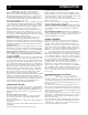

SHUT DOWN / SYSTEM INFORMATION 7
7. SET CHEMICAL INJECTION: If unit is equipped with inlet
chemical injection, place chemical pickup tube in pre-mixed
chemical solution and open chemical valve for desired chemi-
cal concentration. Rinse and close valve after use, do not use
harsh chemicals through the inlet injector system. If unit is
equipped with a downstream chemical injector, connect the
chemical injection assembly into the high pressure discharge
hose quick connects. Place the chemical pickup into chemical
solution and turn brass collar to adjust concentration. The
chemical will inject only when you drop the outlet pressure by
opening the valve on the dual wand or changing to a low
pressure nozzle. Soap the surface from the bottom up. Close
chemical valve when not in use.
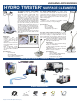
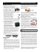
8. If equipped, AF2 (2) gun operation, select "50%"
nozzle from panel and insert into coupler on spray
gun for full pressure output when using two guns at
the same time. Flow can be reduced by selecting flow
reduction nozzles only when one operator is using the
machine. Maximum temperature is 200° F.
SHUT DOWN:
1. TURN BURNER SWITCH TO THE OFF POSITION.
2. RINSE & CLOSE CHEMICAL VALVE.
3. SQUEEZE THE TRIGGER ON THE SPRAY GUN
UNTIL THE WATER BECOMES COOL.
4. TURN MOTOR/ENGINE SWITCH OFF with the
appropriate controls.
5. TURN OFF WATER SUPPLY.
6. SQUEEZE TRIGGER TO RELEASE ANY
TRAPPED PRESSURE IN DISCHARGE HOSE.
7. ANTIFREEZE EQUIPMENT:
In the event that the equipment is not to be used for an
extended period, store in heated space or antifreeze the unit.
Run the machine until the float tank is near empty, fill with
a 50% mix of water and antifreeze and run until antifreeze
appears at the high pressure outlet. If unit is equipped with
a blow out valve, it may be blown out with compressed air
in addition to using antifreeze solution. On direct feed units
(no float tank), use a 5' garden hose to draw the antifreeze
mix from a bucket. Or blow out the unit with compressed
air until only air and no water comes out of the discharge.
CHASSIS & TRAILER ASSEMBLY:
To maintain the appearance of the machine use stainless
steel cleaner on the stainless steel panels.
Check tire air pressure. Check all bolts including the
lug nuts for tightness and condition periodically. Grease
wheel bearings as required and adjust after first month.
TIRE PRESSURE
T3000 T3500 T4500 T5500
35 psi 35 psi 40 psi 45 psi
Be sure that the trailer you order conforms to your particular
State Department of Transportation regulations in effect at
this time, including braking and lighting requirements. If
water is being transported on the highway, trailer brakes are
recommended.
To insure safe trailering, be certain that the hitch on
your tow vehicle is rated for the full trailer weight and of the
proper height so that the trailer remains level when hitched,
or wheel damage could result. DOUBLE CHECK safety
chain, hitch coupler and wire harness before departing.
Check latch on coupler and adjust, if required, to fit your
trailer ball properly.
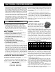
POWER SYSTEMS:
ELECTRIC MOTORS: All single phase
electric motors contain a manual or auto-
matic thermal overload which will shut down
the motor if it overheats. If the overload or
starter shuts down the motor, have an elec-
trician or an authorized Hydro Tek distributor check for electrical
problems. Voltage reading under load should be +/- 10% of
name plate voltage on motor. The motor can be reset by
depressing the red overload button located on either the
motor or the starter, (as shown above). Use thumb pressure
only - DO NOT force. Wait for motor to cool before
resetting. The automatic overload will reset itself after the
motor has cooled. Never spray water on the unit, or damage
to the electric motor(s) may occur. Consult the factory if
running an electric machine from a generator. Three times
total system wattage is required.
A fused disconnect switch of sufficient ampere rating
should be installed by an electrician to provide power to the
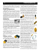
machine. Refer to the chart above for electrical require-
ments: (208 Volt is acceptable, but unit motor must be under
nameplate amps; turn psi down). If your unit is equipped with
a ground fault interrupter, it will have to be reset whenever it
is plugged in, or if a ground fault interruption occurs. Test
regularly for proper operation.
GASOLINE ENGINE: With the proper care and main-
tenance, your gasoline engine will give years of trouble free
service. Please follow the Service and Maintenance Guide
and the enclosed engine sheet or contact your local authorized
engine dealer for maintenance and repairs.
Use unleaded gasoline with an octane rating of 87 or
higher in the engine fuel tank. Consult engine manual for
proper oil type and capacity. Change oil every 50 hours and
the filter every 100 hours (see engine manual).
MAINTAIN PH BETWEEN 5 & 9
A=TOTAL SYSTEM AMPERES
HORSE
POWER
115V
1PH
WIRE
SIZE
208V
1PH
WIRE
SIZE
208V
3PH
WIRE
SIZE
230V
1PH
WIRE
SIZE
230V
3PH
WIRE
SIZE
460V
3PH
WIRE
SIZE
1.5 15A 12/3 N/A N/A N/A N/A 10A 14 N/A N/A N/A N/A
2 20A 12/3 N/A N/A N/A N/A 12A 14 N/A N/A N/A N/A
5 N/A N/A 26A 10/3 N/A N/A 24A 10/3 N/A N/A N/A N/A
6.5 / 6 N/A N/A N/A N/A N/A N/A 27A 10/3 22A 12/4 13A 14/4
7.5 N/A N/A N/A N/A N/A N/A 35A #8 N/A N/A N/A N/A
10 N/A N/A 50A #8 32A #8 48A #8 30A #10 16A #12
15 N/A N/A N/A N/A 40A #8 N/A N/A 38A #8 20A #12