
Operating instructions


8 SYSTEM INFORMATION
Do not rely on the low oil shutdown (if equipped) as a
reminder to add oil. Engine damage from lack of oil will
typically not be warranted even if the low oil system failed.
On machines with a 115V generator or a 12V burner, the
throttle is preset at the factory (See Generator section on this
page for adjustment).
POWER TRANSMISSION:
DIRECT DRIVE: Pump is bolted directly to the motor/
engine. If pump needs to be removed, do not force off by prying
or damage may occur. When reassembling, coat the entire
motor shaft with heavy grease, or a generous amount of anti-
seize and use service removable "lock tight" on mounting bolts.
BELT DRIVE: Check belt condition, alignment and tension
periodically. Replace belts when they show signs of wear or
cracking. Tighten belts by loosening the mounting bolts on the
pump and generator to permit them to slide. Turn the horizontal
rail adjusting bolts to tighten belts until they deflect ¼" to ½" inch
with finger pressure.
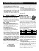
GENERATOR:
Some self-contained Hot Water Units
are equipped with a 115 volt generator to
power the diesel burner. The generator
output voltage must be between 110 to
130 Volts, (or between 59 to 63hz), when
the unit is under full load. If the generator voltage falls out
of this range the RPM of the engine will need to be adjusted
to proper speed. If the engine cannot maintain the
proper RPM do not use the burner or any power from
the generator until the engine is repaired.
A switch/circuit breaker will need to be reset if the circuit
is overloaded.
To extend generator life make sure the burner is off when
the engine is started or stopped. Keep generator dry. Do
not spray off with trigger gun.
If unit is equipped with auxiliary generator power outlets,
they are located on the back of the electrical box. Do not
plug in accessories over 1200 watts or
10 amps.
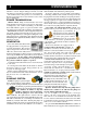
PUMPING SYSTEM:
PUMP: The pump is a positive displace-
ment, oil bath crankcase, triplex plunger
type. It contains 3 plungers which move forward and backward
in a cylinder to propel water past 3 inlet valves and
3 discharge valves into a high pressure manifold.
The crankcase oil window or dip stick
should be checked for oil level and clarity.
Check the pump for oil or water leaks
before each use. The sight window is located at the rear
(opposite the head) of the pump and should be filled to the red dot
with AR recommended oil, or Cat Pump recommended oil
available at your Hydro Tek dealer. Wobble plate pumps use
synthetic oil which only needs to be changed if the oil becomes
contaminated. If the oil becomes milky in color, moisture is
entering the crankcase. Change the oil and contact your
authorized Hydro Tek dealer if the problem persists.
To increase pump life, prevent cavitation (air bubbles),
overheating, and dirty water. Cavitation can be prevented by
keeping filters clean and checking for air in pump feed lines.
Do not run the pump in the bypass mode (pump running with
the trigger gun off), for a period of more than 5 minutes or
the pump will begin to overheat (maximum water tempera-
ture is 145º F). Do not run pump dry. Protect from freezing.
Do not run a frozen pump until it is completely thawed.
UNLOADER AND PRESSURE RELIEF VALVE: The
unloader valve is preset at the factory to govern the proper
output pressure of your machine. It
will release the pressure of the pump
output back into the inlet if the trig-
ger on the spray gun is released.
NEVER increase the set pressure
on the unloader to exceed the specifications for
your machine. The unloader should be adjusted only by
qualified personnel.
All hot water machines are equipped with a
SAFETY PRESSURE RELIEF VALVE. In
the unlikely event that your unloader fails, or if
the burner overheats and builds excessive pres-
sure, the pressure relief valve will vent the
pressure into the atmosphere. If this occurs, turn off the
machine and have it checked by an authorized dealer. The
pressure relief valve will automatically reset itself.
BURST DISK TECHNOLOGY: This addi-
tional safety feature functions to protect the coil
and other components from over-pressurizing
from the heating system and high system spikes
of pressure. If this component ruptures, you
should take the machine in to an authorized
Hydro Tek dealer. Do not plug off and continue to run.
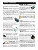
CHEMICAL INJECTION SYSTEM: With an inlet chemical
injection system the chemicals are intro-
duced at the inlet of the pump and con-
trolled with a chemical metering valve.
The pump is fed by a float tank to create
a slight vacuum which draws up the
chemical into the inlet manifold of the
pump, mixes it with the water, and sprays
it out of the nozzle under high pressure.
Open the chemical valve only when the pickup tube is
submersed in a solution or air will enter the pump, lose
pressure, and the pump will run rough.
Do not use highly corrosive detergents or acid type
cleaners. Be sure to rinse and close the chemical valve
after each use or the chemical line and check valve may
become obstructed. Chemicals should be between 5-9PH.
Consult Hydro Tek for chemical compatibility. Chemical
abuse is not covered under warranty.
An optional DOWNSTREAM INJECTOR is available if
harsh chemicals need to be applied. The downstream injector