IPS3000P 3KVA INVERTER / CHARGER Version 1.00 (English) BEFORE GETTING STARTED This document is designed to aid you to get started with the device. If you experience problems following these guides or need further information pertaining to the device, please visit our website at www.prolink2u.com. All specifications are subject to the manufacturer’s configuration at the time of shipping and may change without prior notice, written or otherwise.
CONTENTS ABOUT THIS MANUAL ...................................................................................................................................... 1 Purpose............................................................................................................................................................ 1 Scope ...............................................................................................................................................................
ABOUT THIS MANUAL Purpose The purpose of this manual is to provide explanations and procedures for installing, operating and troubleshooting for the unit. This manual should be read carefully before installations and operations. Please retain this manual for future reference. Scope This document defines the functional requirements of the unit, intended for worldwide use in electronic processing equipment.
11. No AC or DC disconnects are provided as an integral part of this unit. Both AC and DC disconnects must be provided as part of the system installation. See INSTALLATION section of this manual. 12. Fuses (F40AL, 32VDC*6) are provided as the over current protection of the battery supply. 13. GROUNDING INSTRUCTIONS -This battery charger should be connected to a grounded permanent wiring system.
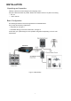
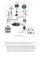
INSTALLATION Unpacking and Inspection Carefully unpack the inverter/charger from its shipping carton. Verify all of items list below are present. Please call customer service if any items are missing. y The unit y 1 user’s manual Basic Configuration The following illustrations show basic applications for IPS3000P 3KVA. They include the following configurations: y Utility Backup.
IPS3000P Figure 2 Renewable Energy Source IPS3000P 3KVA Inverter can feeds almost all kinds of appliances from home to office environment, including motor characteristic appliances like tube light, fan, refrigerator and Air conditioner.
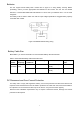
Batteries The unit support 24volt battery bank. Please refer to figure 3 to wiring battery correctly. Before proceeding, ensure you have appropriate size batteries for this inverter. The unit can use flooded lead-acid, or sealed GEL/AGM lead-acid batteries so ensure that your batteries are in one of these categories. The battery must be wired to match the units DC input voltage specifications. Suggest battery capacity not smaller than 100AH.
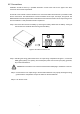
Battery Cable Connection Observe Battery Polarity! Place the ring terminal of DC cable over the bolt and directly against the unit’s battery terminal. Tighten the M6 screw with 5-8 Nm. Do not place anything between the flat part of the Backup System terminal and the battery cable ring terminal or overheating may occur.
AC Connections Installation should be done by a qualified electrician. Consult local code for the proper wire sizes, connectors and conduit requirements. On the left of rear chassis is the AC hardwire cover. Two three-station terminal block is provided to make the AC connections. The terminal block is used to hardwire the AC input, AC output, and ground. The National Electrical Code requires that an external disconnect switch be used in the AC input wiring circuit.
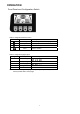
OPERATION Front Panel and Configuration Switch Table 3 configuration button function Switch Function config up Description Enter config mode, and turn page Move up to pre-select down Move down to pre-select enter Enter to confirm Table 4 configuration pages option Page Description Selectable option 1 Input range 2 Output range 3 Battery type 4 Charger current 20A/10A 5 Saver mode ON/OFF 230V Note: There are 5 configuration pages totally, change only active by enter button pressed wit
Indicator & Alarm Charger mode battery indicator Battery capacity segment will lighting to comply with battery voltage Status CC/CV Battery voltage(+/-0.6V) >26V 25V~26V 24V~25V Floating 21V~24V Any battery voltage <21V Inverter mode battery indicator: Battery voltage(+/-0.6V) >26V 25V~26V 24V~25V 23V~24V 21.6V~23V -- -- -- -- -- ALARM 20V~21.
Operating Indicators Standby Mode: Inverter Mode: Voltage and Frequency exchanged every 5 seconds Voltage and Frequency exchanged every 5 seconds Line Mode: Warning Mode: Voltage and Frequency exchanged every 5 seconds Red back light flash every 1 second “OVLD”: Overload Warning “BATT”: Battery Low Warning “FAN”: Fan Abnormal Warning Saver Mode: Fault Mode: Output Voltage display flash every 1 second Red back light Keep on 10
Setting Indicators 11
SPECIFICATIONS Table 5 Line Mode Specifications MODEL IPS3000P Input Voltage Waveform Sinusoidal (utility or generator) Nominal Input Voltage 230Vac 170Vac±4%(NOR) Low Line Disconnect 90Vac±4%(GEN/WID) 180Vac±4% (NOR) 100Vac±4% (GEN/WID) Low Line Re-connect Note: 1.NOR setting can be used for general electrical appliance 2. WID setting can be used only for some special load, such as lamp, fan.
Table 6 Invert Mode Specifications MODEL IPS3000P Output Voltage Waveform Pure Sine Wave Rated Output Power 3000VA Power Factor 0.
Table 7 Charge Mode Specifications Nominal Input Voltage 230Vac Input Voltage Range 180V - 270Vac(NOR) 100V - 270Vac(GEN/WID) High Voltage Disconnect 280Vac±4% High Line Re-connect 270Vac±4% 170Vac(NOR) 90Vac(GEN/WID) 180Vac±4% (NOR) Low Voltage Disconnect Low Line Re-connect 100Vac±4% (GEN/WID) Nominal Output Voltage Refer to Charge Algorithm/ Battery Type Setting Nominal Charge Current 10A @Vi/p<170Vac 20A@Vi/p=230Vac 10A @Vi/p>280Vac Charge current tolerance ±10% Over Charge Protection B
Table 8 Approximate Back-up Times Load(VA) 100Ah 24VDC(min) 200AH 24VDC(min) 300 457.5 972.2 600 208.1 499.5 900 140.6 262.3 1200 103 178.1 1500 77.8 138.3 1800 57.6 113.2 2100 49.5 100.5 2400 41.4 87.9 2700 33.2 75.3 3000 28.4 62.6 Note: Back-up times depend on the quality of the battery, age of battery and type of battery. Specifications of batteries vary from one manufacturer to another.
Table 10 Fault code/ Audible alarm Fault Protect Code Function Active Mode Warning (O/P=ON) Condition -- Low DC Voltage Alarm 0 Low DC DC VoltageHigh DC input Voltage Standby Shut-down Protection 2 Line/ 110%~150% load Over Load Inverter Protection Line/ >150% load Inverter Inverter DC voltageHigh DC input Shut-down 3 Output 1)Output Voltage<20Vrms Short Inverter Circuit 2)
TROUBLE SHOOTING Problem Possible Causes Remedy 1. Battery Weak 1. Re-charge battery 2. Battery defective (can't be 2. Battery replacement charged) No LCD display 3. Power switch is not pressed 3. Press and hold power switch 4. Battery polarity reversed, can’t start up the unit Mains normal but works in inverter mode Mains normal but 4. Sent back for repair 1. AC Input missing 1. Check AC input connection 2. Input protector is effective 2. Reset the input protector 1.
Register Online For Your Product Warranty @ www.prolink2u.com/register PROLiNK® is a trademark of FIDA INTERNATIONAL (S) PTE LTD and is manufactured under its authority. All other brands, products, services, logos and company names mentioned herein are trademarks of their respective owners. All specifications, designs and contents are subject to changes without prior notice. © Copyright 2012. PROLiNK® all rights reserved.