IPS5000 5KVA INVERTER / CHARGER Version 1.00 (English) BEFORE GETTING STARTED This document is designed to aid you to get started with the device. If you experience problems following these guides or need further information pertaining to the device, please visit our website at www.prolink2u.com. All specifications are subject to the manufacturer’s configuration at the time of shipping and may change without prior notice, written or otherwise.
Contents ABOUT THIS MANUAL ........................................................................................................................................ - 2 Purpose................................................................................................................................................................ - 2 Scope ...................................................................................................................................................................
ABOUT THIS MANUAL Purpose This purpose of this manual is to provide explanations and procedures for installing, operating and troubleshooting for the unit. This manual should be read carefully before installations and operations. Please retain this manual for future reference. Scope This document defines the functional requirements of the unit, intended for worldwide use in electronic processing equipment.
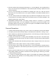
9. Be extra cautious when working with metal tools on, or around batteries. The potential exists to drop a tool and short-circuit the batteries or other electrical parts resulting in sparks that could cause an explosion. 10. No AC or DC disconnects are provided as an integral part of this unit. Both AC and DC disconnects must be provided as part of the system installation. See INSTALLATION section of this manual. 11.
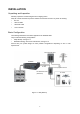
INSTALLATION Unpacking and Inspection Carefully unpack the inverter/charger from its shipping carton. Verify all of items list below are present. Please call customer service if any items are missing. y The unit y 1 DC red cable y 1 DC black cable y 1 user’s manual Basic Configuration The following illustrations show basic applications for IPS5000 5KVa. They include the following configurations: y Utility Backup.
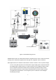
Photovoltaic Hydro Wind DC Combiner Box DC Disconnect DC Diversion Load (for Wind Generator) DC Disconnect and PVGFP DC Disconnect Diversion Load Controller DC Diversion Load (for Hydro Generator) Diversion Load Controller DC Charger Controller AC Generator Conduit (if used) Generator Disconnect IPS5000 Inverex S 5KVA DC Disconnect AC I/P AC O/P Vent (outlet) AC Loads Battery Enclosure (if used) Vent (inlet) To Primary System Ground Battery Bank Figure 1-2 Renewable Energy Source IPS500
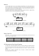
Batteries The unit support either 48 volt or 96 volt battery bank depending on the model. Please refer to figure 2 to wiring battery correctly. Before proceeding, ensure you have appropriate size batteries for this inverter. The unit can use flooded lead-acid, or sealed GEL/AGM lead-acid batteries so ensure that your batteries are in one of these categories. The battery must be wired to match the units DC input voltage specifications.
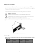
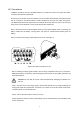
Battery Cable Connection Observe Battery Polarity! Place the ring terminal of DC cable over the bolt and directly against the unit’s battery terminal. Tighten the M8 screw to 5-8 Nm. Do not place anything between the flat part of the Backup System terminal and the battery cable ring terminal or overheating may occur.
AC Connections Installation should be done by a qualified electrician. Consult local code for the proper wire sizes, connectors and conduit requirements. On the left of rear chassis is the AC hardwire cover. A six-station terminal block is provided to make the AC connections. The terminal block is used to hardwire the AC input, AC output, and ground. The National Electrical Code requires that an external disconnect switch be used in the AC input wiring circuit.
OPERATION Front Panel Controls and LCD Indicators Shown below figure 5 are the controls and indicator lights on the front of the unit. They control and provide information in either inverter or battery charging mode of operation. LCD indicator On/Off Configuration switch switch Figure 5 Front Panel Power ON/OFF Located on the left of the panel is the ON/OFF Switch. Once the unit has been properly installed and the batteries are connected, press this switch to on position will turn on the unit.
LCD Indicator Comprehensive LCD display provides system status, and user-friendly panel eases program settings. See Figure 6. Figure 6 LCD display interface y AC Mode Indicator The line mode symbol will show up and the indicator present input voltage, output voltage, load information. y Inverter Mode Indicator The inverter mode symbol will show up and the indicator present input voltage, output voltage, load information.
y Load indicator The load indicate the load percentage comply with load VA or W(show the bigger value), the overload label will flash when overload exist. Battery Charger y Inverter to Charger Transition The internal battery charger and automatic transfer relay allow the unit to operate as either a battery charger or inverter (but not both at the same time). The unit automatically becomes a battery charger whenever AC power is supplied to its AC input.
SPECIFICATIONS Table 5 Line Mode Specifications MODEL IPS5000R IPS5000L Sinusoidal (utility or generator) Input Voltage Waveform 230Vac Nominal Input Voltage High Line Disconnect 170Vac (Normal) 90Vac (generator/Wide range) 180Vac (Normal) 100Vac (generator/Wide range) 280Vac High Line Re-connect 270Vac Max AC Input Voltage 300Vac rms Low Line Disconnect Low Line Re-connect 50Hz / 60Hz (Auto detection) Nominal Input Frequency 40±1Hz Low Line Frequency Disconnect Low Line Frequency Re-connec
Table 6 Inverter Mode Specifications MODEL IPS5000R IPS5000L Output Voltage Waveform Pure Sine Wave Rated Output Power(VA) 5000 Power Factor 0.84 230Vac Nominal Output Voltage(V) 50Hz / 60Hz ± 1Hz Output Frequency(Hz) ±10% rms Output Voltage Regulation >90% fault after 5s@≥150% load, fault after 10s@110%~150% load, 10000VA Nominal Efficiency Over-Load Protection Surge rating 2.
Table 7 Charge Mode Specifications MODEL IPS5000R IPS5000L 230Vac Nominal Input Voltage 180V~ 270Vac(Normal range) 100V~ 270Vac(generator/wide range) Input Voltage Range According to the battery type Nominal Output Voltage Nominal Charge Current 20A(95-175v,gen/wide,only), 35A(175-275v)@35A setting 20A(175v-275v)@20A setting) 10A(95-175v,gen/wide,only), 20A(175-275v)@20A setting 10A(175v-275v)@10A setting) >35Vdc >70Vdc Battery initial voltage(sps setup) Unit shutdown automatic Charger Short C
Table 8 General Specifications Safety Certification CE(EN60950) EMI Classification EN62040-2, CLASS A Operating Temperature Range 0°C to 45°C Storage temperature -15°C ~ 60°C Altitude, operational Elevation: 0 ~ 1500 Meters Relative humidity 5% to 95% non-condensing Audible Noise 60dB max Cooling Forced air, variable speed fan Dimension 350mm(W)*110mm(H)*407mm(D) Net Weight 9KG Table 9 Fault code/ Audible alarm Fault Code -0 Protect Function Low DC Voltage Alarm Low DC Voltage Protectio
TROUBLESHOOTING Problem No LCD display Mains normal but works in inverter mode Possible Causes 1. Battery Weak (<35V for IPS5000R, <70V for IPS5000L) 2. Battery defective (can't be charged) 3. Power switch is not pressed 4. Battery polarity reversed, can’t start up the unit 1. AC Input missing 2. Input protector is effective 1. Overload 2. Output short circuit 3. Over temp 4. Over charger Alarm buzzer beeps continuously 5. Over voltage 6. Fan fault 7. Back-EMF 8.
Register Online For Your Product Warranty @ www.prolink2u.com/register PROLiNK® is a trademark of FIDA INTERNATIONAL (S) PTE LTD and is manufactured under its authority. All other brands, products, services, logos and company names mentioned herein are trademarks of their respective owners. All specifications, designs and contents are subject to changes without prior notice. © Copyright 2012. PROLiNK® all rights reserved.