
Manual


- 9 -
OPERATION
Front Panel Controls and LCD Indicators
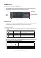
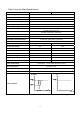
Shown below figure 5 are the controls and indicator lights on the front of the unit. They control and
provide information in either inverter or battery charging mode of operation.
Figure 5 Front Panel
Power ON/OFF
Located on the left of the panel is the ON/OFF Switch. Once the unit has been properly installed
and the batteries are connected, press this switch to on position will turn on the unit.
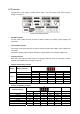
Configuration Switch
On the right of panel is the 4 configuration switches which setup unit operation parameter. See table
3 for details.
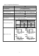
Switch Function Description
up Move up to pre-select
down Move down to pre-select
configuration Enter configuration mode, and turn page
enter Enter to confirm
Table 3 configuration button function
After you press configuration button and enter configuration mode, there are 4 configuration pages
totally. Turn page by press configuration button again.
Page Description Selectable option
1 Input range Normal/generator/wide range
2 Output range 220v/230v/240v
3 Battery type AGM/GEL/FLOODED
4 Charger current 35A/20A(IPS5000R) 20A/10A(IPS5000L)
5 Saver mode ON/OFF
Note: The 220v and 240v output function is reversed for further feature.
Table 4 configuration button function
On/Off
switch
LCD indicator
Configuration switch