
User Manual


18
Operation
Inverter Power On and Off
When AC shore/station power is provided to the AC input of the inverter, the unit operates in pass-
through mode. When AC shore/station power is not present, the unit will switch over to inverter
mode. In this mode, the AC output can be turned on or off by pressing the ON/OFF button on the
display panel. With the remote feature, the inverter can be turned on or off remotely as well. See
page 7 for a detailed explanation of the modes.
15A GFCI Outlet Breaker
In pass-through mode, the maximum AC current allowed through this outlet is 15A. Once the pass-through
AC current exceeds 15A, the breaker will trip. User must allow 5 minutes for the breaker to cool and verify
the loads are less than 15A before resetting it by pushing the breaker to its normal position.
GFCI Testing
To test the GFCI, start by plugging a load such as a lamp into the outlet. Press the TEST button to shut
power off to the load. If the load turns off, then this part of the test is a pass. Next, press the RESET
button. If power is restored to the load, then this test is a pass and verifies the functionality of the GFCI.
Operating the Inverter within the Load Range
Load Type Precautions
Resistive Loads - Be careful with resistive loads that generate heat (toasters, electric stoves, etc.). Due
to the high current drawn by these loads, a typical battery bank would be drained very quickly. Therefore,
it would be impractical to run the inverter with these types of loads for an extended period of time.
Motor Loads - Use caution with the type of motor that you connect the inverter. Induction motors require a
much higher startup current than their running current. Since motors vary in their characteristics, it is best
to test the motor load on the inverter. If the motor does not start or loses power, the inverter should be turned
off and the motor removed. If the motor startup current is too high, the inverter will turn itself off.
Important Notice: FCC Class B Part 15 Notification
NOTE: This equipment has been tested and found to comply with the limits for a Class B digital device, pursuant
to Part 15 of the FCC Rules. These limits are designed to provide reasonable protection against harmful interference
when the equipment is operated in a commercial environment. Operation of this equipment in a residential area
is likely to cause harmful interference in which case the user will be required to correct the interference at their
own expense. If in a residential setting you are encountering interference with TV and Radio reception while NOT
in inverter mode, then: simply disconnect AC power from the TruePower Plus Inverter to confirm if this unit is
causing the interference, if so explore the following options to minimize interference:
1) Make sure your AC connections include a proper ground connection
2) Reposition your receiving antenna
3) Purchase a separate AC line filter
4) Relocate the affected appliance so it is further separated from the TruePower Plus Inverter
This equipment has been designed to comply with:
- American Boat & Yacht Council A-31 Battery Chargers and Inverters
- FCC Class B
- Underwriters Laboratories: Standard 458 Power Converter/Inverter Systems for
Land Vehicles and Marine Crafts
- Certified to CSA STD. C22.2 No. 107.2
OPERATION
17
INSTALLATION
Installation (Continued)
1) DC Cables - The DC portion of the TruePower Plus Inverter requires a large amount of amperage in Inverter
mode. Cable size and length is of extreme importance and should be well thought out and planned per this
manual before beginning installation. Items to consider are as follows:
a. Cable Size - For boating applications size is based on amperage draw of the unit compared to the
maximum amperage a cable can carry based on ABYC E-11. For RV installations reference ANSI/RVIA
or the appropriate electrical standard should be used. On Board Solutions recommends NO MORE
THAN a 10% drop in voltage from source (battery) to the TruePower Plus unit or a cable run not
longer than 5 feet.
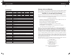
The following table outlines the cable size based on a 5’ out and 5’ back (10’ round trip cable run).
Recommended cable sizes (Based on UL 1426 105° C jacket temperature rating and a class T or
ANL style fuse).
b. Termination - Larger DC cables require specialty tools to ensure proper termination with ring terminals.
Pre-terminated cable kits can be purchased through On Board Solutions or your local marine supply
store. Cable type is as important as size. Cables for boating applications shall be acceptable under
ABYC E-11 AC & DC Electrical Systems (types such as UL 1426 Boat Cable and SAE J1127 Battery
Cable are common and marked as such). For RV applications consult the SAE standard J1127 or
J1128 or NEC table 310-104(A) or equivalent.
c. Connection - The ring terminal must be directly on the battery terminal surface of the DC studs on
the TruePower Plus Inverter, followed by the washer and nut with a torque of 10-15 foot-pounds.
The use of a dielectric or anti-oxidant paste is recommended once the cables have been connected.
d. Strain Relief - Install proper strain relief within 6" of inverter to prevent weight and vibration of large
cables from damaging the inverter.
e. Installi
ng DC Safety Fuse - Install fuse in positive (+) cable. For an ABYC E-11 compliant installation,
the fuse shall be within 7" of the battery connection. For an ANSI/RVIA compliant installation, the fuse
shall be within 18" of the battery connection. See above table for recommendation fuse.
DO NOT ATTEMPT CABLE TERMINATION BY MEANS OTHER THAN PROPER CRIMPING, WITH A PROPERLY
CALIBRATED TOOL. SOLDER AND AUTOMOTIVE REPAIR TYPE BATTERY TERMINALS ARE NOT ACCEPTABLE.
USE OF ANY OF THESE TYPES OF TERMINATIONS WILL RESULT IN PREMATURE, UNWARRANTIED FAILURE
OF THE TRUEPOWER UNIT.
2) AC Cables - For boating applications, AC Cables should be UL 1426 Boat Cable, per ABYC
E-11. For RV applications consult the SAE J1127 or J1128 or the NEC table 310-104(A) or equivalent. This
type of cable is readily available in both 2 and 3 conductor. Size is based on the maximum amperage to be
passed through the cable and unlike DC does not take into account the length of the cable run and voltage
drop. The table below indicates the proper size for AC Cables.
a. AC Connections - Screw terminal blocks have been provided to connect the input and output
AC cables. Tighten the AC screw terminal blocks to 7 in-lbs.
Shore/Station Power Service Cable Size (AWG) 105° C Insulation
30 amp 10
Wattage 12 VDC Amp Draw 5’ Length Cable Size (AWG) 12V Recommended Fuse DC Stud Size
1000 100A 4 150A 1/4”
1200 120A 2 175A 1/4”
1500 150A 1 200A 1/4”
2000 200A 00 250A 5/16”