
User Manual


13
INSTALLATION INSTALLATION
AC Wiring Options
Installation Diagrams
WARNING - AC Installations have the potential to cause serious injury or death.
Installations should be performed by a Certified Electrical Technician to ensure a safe
and trouble free installation.
Depending on the appliances and loads that are intended to be powered by the TruePower Plus
Inverter, there are essentially 2 installation options:
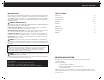
1) TRANSFER TO ALL LOADS - This scenario allows the entire AC panel board to be powered by
the TruePower Plus Inverter. This is the simplest installation for an existing AC panel board. This
scenario enables the user to choose what will be powered by the TruePower Plus Inverter. Energizing
the entire panel may overload the unit depending on the size and the load requested. The diagram
below, provided from ABYC found in A-31 battery chargers and inverters, explains this scenario.
Advantages - Multiple loads from the existing panel board can be chosen, the user is not locked
into set loads. This may require more trial and error to determine which loads the TruePower Plus
Inverter can run.
14
* Note: Unlike household wiring, the neutral (N) and ground (G) are only connected
together at the SOURCE of power, either inverter or shore/station power. The
TruePower Plus transfer switch maintains this wiring scheme automatically.
TruePower Plus
Inverter
Case Ground/Earth
DC
AC
OUT
AC
IN
DC Positive Fuse or Breaker
Double Pole
AC Main Breaker
Ground
Bus/
Engine
Negative
12V Battery
Connection
Panel
Ground
Bus
Panel
Neutral
Bus
AC Panel
Lights
TV
Coffee Maker
Electric Grill
Microwave
Circuit
Breaker
Shore/
Station
Power
IN
N (White)
G (Green)
L (Black)
G
N
L
N
G
12V Battery
7" per ABYC or 18" per ANSI/RVIA
(Black)
(Red)
L
Fuse