
Owner manual


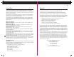

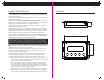

Dimensions
ProNauticP 12volt 10-40 Amp and 24 volt 20 Amp Dimensions Inches (mm)
9
Installation
CAUTION: Make sure AC Shore Power is Disconnected from the Boat and there is no presence
of AC Power prior to installation. For new installations always connect Batteries as the LAST STEP.
If you are replacing an existing battery charger please disconnect the battery charger output cables
from the existing charger AND the battery(s). Do not use existing cables if they are not in compliance
with the sizes detailed in this manual. If you have any doubt about your ability to fuse and wire
this unit correctly PLEASE refer to for a list of certified electricians in your area that are qualified
to perform this installation to the ABYC Standards.
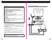
1. Permanent Installation and Circuit Protection - This charger is designed for permanent
installation, the AC must be permanently wired to the circuit breaker (dedicated or a branch
breaker in a panel) in order to avoid serious injury or death.The following table indicates which
breaker & conductor size is appropriate for the model installed. Use only UL 1426 “Boat Cable”
with a jacket temperature rating of 105°C, this is commonly available at any marine supply
store. Do not use solid cable, speaker wire or welding cable.
Note: Common Breaker sizes are 5, 10, 15, 20 amp for example if charger is listed below as
6 Amp at 110 VAC please use a 10 amp breaker.
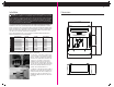
* These units (1250, 1260, 2430,) require the installation of a split ferrite unit included in
the package. It is installed on the AC input cable as shown below.
22
Charger Model 110-120 220-250 AC conductor
volt breaker volt breaker size
ProNautic1210P 5 Amp 5 Amp 16 AWG
ProNautic1215P 10 Amp 5 Amp 16 AWG
ProNautic1220P 10 Amp 5 Amp 16 AWG
ProNautic1230P 10 Amp 10 Amp 16 AWG
ProNautic1240P 15 Amp 10 Amp 14 AWG
ProNautic1250P* 15 Amp 10 Amp 14 AWG
ProNautic1260P* 15 Amp 10 Amp 14 AWG
ProNautic2420P 15 Amp 10 Amp 14 AWG
ProNautic2430P* 15 Amp 10 Amp 14 AWG
AC Breaker Sizing
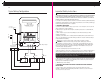
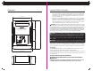
2. Connections – Using ring or captive spade
connections and the proper crimping tool, attach
the Line – Neutral – Ground to the appropriate
terminals on the charger (Note: Label above AC
connector is color coded to ensure proper
installation). Repeat this procedure for the
breaker side of the install. Support cable every
18” and protect from sharp edges and chafing
when passing through bulkheads, and other
openings all according to ABYC E-11.
3. Split Ferrite - This split ferrite unit is included
with models 1250, 1260 and 2430. It must be
installed such that all of the AC cabling passes
through it as shown. The split ferrite is to be
installed immediately before the AC cable enters
the charger.
ProNautic 12
•
40 P
Power Factor Corrected & Global AC Input
3 1/2” (90 mm)
7 3/4” (198 mm)
3 1/2” (90 mm)
8 1/2” (215 mm)
3 3/8” (85 mm) 3 3/8” (85 mm)
10 1/4” (260 mm)