
User Manual


19
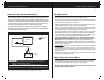
Charging Your Batteries
Optional Battery Bank Status Monitor
See your local dealer or retailer for the ProMariner Remote Battery Bank Status Monitor.
The Remote Monitor is easy to install and connects directly to your boat’s batteries.
Once installed, simply hold down the "Push-To-Test" button and observe the charge
level indicator for each battery (up to 3 batteries can be monitored).
Note: AC power to the battery charger and the boat’s engine must be off when using
the Remote Battery Bank Status Monitor.
Charging Batteries
The ProSport Series is designed to charge, condition, and maintain your batteries.
Please follow these steps each time you use your ProSport Charger:
1. Open all battery compartments and ventilate for at least 15 minutes before applying
AC power to your charger. While charging your batteries make sure to keep your battery
compartment open allowing for free air ventilation.
2. Make sure all DC battery connections are tight and clean. Follow battery manufacturer's
recommendations for battery cell caps. (loosen caps if applicable)
3. Connect a heavy duty UL approved extension cord to the ProSport Charger first. After
connecting the extension cord to the charger, proceed to plug the extension cord to a
nearby 120VAC GFCI protected (Ground Fault Circuit Interrupt) outlet.
4. Assuming your batteries are discharged, and your ProSport is factory set for standard
Flooded (Lead-acid) batteries, you should observe ProSport's Blue AC POWER LED
Turn On, followed by the Red Charge LED and RED Battery Type LED Turning On (red
is the factory setting of standard Flooded (Lead-acid)/AGM type batteries).
5. The Sequential Multi-Stage Charging Process is complete when only the Green
READY LED and the Blue AC POWER LEDs remain on indicating that your batteries are
fully charged and are being maintained with a precision 13.4 Volts DC Finishing
Voltage(Factory set charge profile for standard Flooded (Lead-acid / AGM Batteries).
ProSport’s Ready/Maintenance Mode is perfect for short or long term storage and will
never overcharge your batteries.
Performance Tip: For long term or winter storage/maintenance of batteries, ProMariner
recommends that every 30 days: AC power is removed by unplugging your extension
cord at the GFCI outlet first, Check battery electrolyte levels. Re-apply AC power to your
ProSport Charger. This practice will properly maintain your batteries resulting in extended
battery life and use.
6. When you are ready to use your boat, unplug your extension cord at the GFCI outlet
first, followed by unplugging the charger.
18
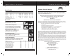
ProSport Series Typical Installation Wiring Diagrams
Installation Guidelines
Engine Crank Battery
Fig. 8 ProSport 6 Single Output Charger for 1 12V Battery
Dedicated 12 VDC Trolling Motor, House or Engine Battery Configuration
Installation Tip:
When connecting each jacketed battery charger cable, make sure it is
connected to only one 12 VDC battery and observe the polarity and color of all connections:
Red Wire = + (Positive) Battery connection
Yellow Wire =
-
(Negative) Battery connection; a black wire is also (-).
The yellow Wire can never be connected to a terminal with red wires. Only black.
Important: The Pair of Red and Yellow wires in one cable jacket MUST GO TO THE SAME 12VDC Battery.
Indicates Jumper Series
Note:
Indicates Fuse
Top View
of Battery
red
yellow
+
_
AC power
Output 1
ProSport6
Bat 1
Cable 1
Note 1: One bank cable connects to no more than one battery
Note 2: ProSport is designed to be used with group 24, 27, 30 and 31 batteries
Note: Incorrect wiring will result in reverse polarity or high reverse voltage,
in the event this happens, the ProSport Charger has been designed to not
fail as a result, however it will cause the charger to "internally disconnect"
and provide "no output" until the (reverse polarity) caused by putting the "Red"
+ lead on a - negative battery terminal) and/or the (high reverse DC voltage
caused by taking one bank cable and spreading it across two batteries) is
corrected, using the wiring diagrams as shown on pages 10-18.
For single battery installations of multi output units double up the outputs.
All Positive connections to the Positive post of the battery and all Negatives
to the Negative post of the battery.