FASTTRAK TX4000 USER MANUAL Version 1.
FastTrak TX4000 User Manual Copyright © 2002 Promise Technology, Inc. All Rights Reserved. Copyright by Promise Technology, Inc. (Promise Technology). No part of this manual may be reproduced or transmitted in any form without the expressed, written permission of Promise Technology. Trademarks Promise, and the Promise logo are registered in U.S. Patent and Trademark Office. All other product names mentioned herein may be trademarks or registered trademarks of their respective companies.
Contents Chapter 1: Introduction........................................................................................ 1 What is the FastTrak TX4000 RAID Card? .................................................. 1 Promise Array Management Utility (PAM).................................................... 2 Keys Features and Benefits ......................................................................... 3 Chapter 2: Quick Start...............................................................................
FastTrak TX4000 User Manual Existing Windows 2000 .............................................................................. 39 Confirming Windows 2000 Driver Installation............................................. 39 New Windows ME Installation .................................................................... 40 Existing Windows ME Installation............................................................... 41 Confirming Driver Installation in Windows ME............................................
Chapter 1: Introduction The PC which you are using either already contains a Promise Technology FastTrak TX4000 RAID card installed by a third-party or you have acquired a FastTrak TX4000 retail product for your existing PC and will be installing the card yourself. • • • For PC owners wishing to install their Promise Technology FastTrak TX4000 card, proceed to Chapter 2: Quick Start on page 5.
FastTrak TX4000 User Manual All FastTrak TX4000 models also offer fault tolerant, data redundancy for entrylevel network file servers or simply for desktop PC users wanting to continually protect valuable data on their PC. Each FastTrak TX4000 model offers RAID 1 mirroring (for two drives) and RAID 0+1 mirroring plus striping (for four drives) to protect data.
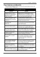
Chapter 1: Introduction Keys Features and Benefits The following information offers an overview of the major features of your new Promise FastTrak TX4000 card... Advanced Hardware Design Features Benefits Supports 66MHz PCI bus motherboards (automatically backward compatible with 33MHz PCI slots) Allows maximum data transfers of up to 266MB per second (133 MB/s in 33 MHz slot) over the bus to dramatically reduce the time to save and retrieve large files.
FastTrak TX4000 User Manual Mirroring supports automatic background rebuilds Fault tolerance can be restored automatically without rebooting. Compatibility Features Benefits Complies with PCI v2.2 Local Bus standard Provides highest level of hardware compatibility. Compliant with PCI IDE Bus Master standard. PCI IDE Bus Master support for Windows 98, ME, NT4, 2000, XP, Server 2003 Provides 32-bit I/O, IDE Bus Master, and Ultra ATA performance for optimal system performance.
Chapter 2: Quick Start When you receive the FastTrak TX4000 Series Controller Card, the package should contain the items listed below: FastTrak TX4000 Ultra ATA/133 RAID Controller Card Quick Start Guide FastTrak TX4000 driver diskette Two Y-cable power splitters. Four internal 80-wire/40-pin Ultra ATA/133 hard drive cables (18 inches or 45 cm in length) • CD with Promise Array Management (PAM) utility, PAM User Manual and FastTrak TX4000 User Manual.
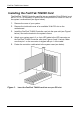
FastTrak TX4000 User Manual Installing the FastTrak TX4000 Card The FastTrak TX4000 Controller card fits into any available 32-bit PCI slot (must be PCI 2.1 or 2.2 compliant). It also fits the 32-bit portion of a 64-bit PCI slot, on the system’s motherboard (see figure below). 1. Remove the cover of your system. 2. Remove the inside slot cover of an available 32-bit PCI slot on the motherboard. 3. Install the FastTrak TX4000 Controller card into the open slot (see Figure 1 below).
Chapter 2: Quick Start Installing the Hard Drives Important If you wish to include your current bootable ATA drive using the Windows NT4.x, 2000, XP, Server 2003, ME or 98 operating system on your FastTrak TX4000 Controller card, do NOT connect the hard drive to the card yet. You MUST install the Windows NT4.x, 2000, XP, Server 2003, ME or 98 driver software first onto this drive while it is still attached to your existing hard drive controller.
FastTrak TX4000 User Manual IDE 2 IDE 1 IDE 4 Figure 2. IDE 3 LED Pin 1 TX4000 card Important You must use an 80-wire, 40-pin cable when connecting your hard drives to the FastTrak TX4000 controller card. The FastTrak TX4000 package contains four 80-wire, 40-pin cables. Notes • • The FastTrak TX4000 Controller card is a PCI Plug-n-Play (PnP) device. No changes are necessary in the Motherboard CMOS Setup for resources or drive types in most applications.
Chapter 2: Quick Start Creating Your Disk Array You will now use the onboard FastBuild BIOS utility to create your array using the attached drives. There are three different scenarios in creating this array. You can create an array for performance, you can create a Security array using new hard drives (recommended), or you can create a Security array using an existing hard drive and a new hard drive. Warning If creating a Security array using an existing hard drive, backup any necessary data.
FastTrak TX4000 User Manual FastBuild (tm) Utility 1.xx (c) 2002-2005 Promise Technology, Inc. [Auto Setup Options Menu] Optimize Array for: Typical Application usage: Performance A/V Editing [ Auto Setup Configuration ] Mode ........................................................... Stripe Drives used in Array........................................... 2 Array Disk Capacity....................................
Chapter 2: Quick Start Creating a Security Array with New Drives Notes Under the Security setting, FastTrak TX4000 permits two drives to be used for a single Mirrored array or four drives to be used for a Mirrored/Striped array in Auto Setup. When creating a Security array with new drives, a feature called Gigabyte Boundary will automatically be set to ON. For a description of the Gigabyte Boundary feature, see page 23. To create an array for data protection using new hard drives, follow these steps: 1.
FastTrak TX4000 User Manual Creating a Security Array with an Existing Data Drive Under the Security setting, FastTrak TX4000 permits two drives to be used for a single Mirrored array or four drives to be used for a Mirrored/Striped array in Auto Setup. You would use this method if you wish to use a drive that already contains data and/or is the bootable system drive in your system. You will need another drive of identical or larger storage capacity.
Chapter 2: Quick Start Channel: Drive ID Source Disk Drive Model Capacity (MB) Channel: Drive ID Target Disk Drive Model Capacity (MB) [Please Select A Source Disk] Channel: Drive ID Drive Model 1: 1 QUANTUMCR8.4A 3: 3 QUANTUMCR8.4A Capacity (MB) 8063 8063 [↑] Up [↓] [ESC] Exit [Ctrl-Y] Save 4. Press the arrow keys to choose which drive contains the existing data to be copied. 5. Press Ctrl-Y to Save selection and start duplication. The following progress screen will appear.
FastTrak TX4000 User Manual 14
Chapter 3: Using FastBuild Configuration Utility The FastBuild Configuration Utility offers several menu choices to create and manage the drive array on the Promise FastTrak TX4000 adapter. For purposes of this manual, it is assumed you have already created an array in the previous chapter and now wish to make a change to the array or view other options.
FastTrak TX4000 User Manual Navigating the FastBuild Setup Menu When using the menus, these are some of the basic navigation tips: Arrow keys highlights through choices; the Space bar allows to cycle through options; Enter selects an option; Esc aborts or exits the current menu. Using the Main Menu This is the first option screen when entering the FastBuild Setup. FastBuild (tm) Utility 1.xx (c) 2002-2005 Promise Technology, Inc.
Chapter 3: FastBuild Configuration Utility Creating Arrays Automatically The Auto Setup (1) selection from the Main Menu can intuitively help create your disk array. It will assign all available drives appropriate for the disk array you are creating. After making all selections, press Ctrl-Y to Save the selections. FastBuild will automatically build the array. FastBuild (tm) Utility 1.xx (c) 2002-2005 Promise Technology, Inc.
FastTrak TX4000 User Manual Optimize Array for Select whether you want Performance (RAID 0), Security (RAID 1 or RAID 0+1) under the Optimize Array for setting. Performance RAID 0 (Striping) supports the high performance. The storage capacity equals the number of drives times the capacity of the smallest drive in the disk array. Note FastTrak TX4000 permits striped arrays using 1, 2, 3, or 4 drives attached in Auto Setup mode.
Chapter 3: FastBuild Configuration Utility Using a Hot Spare Drive If a third drive is attached and is not assigned to a mirrored two-drive disk array (one optimized for Security), it will be recognized as a spare drive. Such a drive is immediately used as a standby replacement. It is automatically added to an array once a disk member of the array has been detected as failed.
FastTrak TX4000 User Manual Viewing Drive Assignments The View Drive Assignments (2) option in the Main Menu displays whether drives are assigned to a disk array or are unassigned. Under the Assignment column, drives are labeled with their assigned disk array or shown as Free if unassigned. Such Free drives can be used for a future array or used as a spare drive when a drive fails in a mirrored array, provided the free drive’s capacity is equal to or larger than the smallest array member.
Chapter 3: FastBuild Configuration Utility Manually Creating an Array The Define Array (3) option from the Main Menu allows users to begin the process of manually defining the drive elements and RAID levels for one or multiple disk arrays attached to FastTrak TX4000. Users will commonly create one or two drive arrays with FastTrak TX4000, though the card will support a maximum of four arrays. You may use a single drive in striping mode with FastTrak TX4000.
FastTrak TX4000 User Manual Selecting Array Type 1. Under the Definition section of this menu, highlight the Array # for which you want to assign a RAID level. 2. Press the Spacebar to cycle through three array types: • Performance (RAID 0 Striping) • Security (RAID 1 Mirroring • RAID 0+1 Striping/Mirroring (for 4 drives) See page 50 for more information about RAID levels. FastBuild (tm) Utility 1.xx (c) 2002-2005 Promise Technology, Inc.
Chapter 3: FastBuild Configuration Utility Gigabyte Boundary The Gigabyte Boundary feature is designed for mirrored arrays (RAID 1 or RAID 0+1) in which a drive has failed and the user cannot replace the drive with the same capacity or larger. Instead, the Gigabyte Boundary feature permits the installation of a replacement drive that is slightly smaller (within 1 gigabyte) than the remaining working drive (for example, an 80.5 GB drive would be rounded down to 80 GB).
FastTrak TX4000 User Manual Creating a Mirrored Array Using New Drives As described in the Drive Assignments Option section above, if you selected a mirroring array and wish to use two new assigned drives, follow the directions here. 1. Assign new drives to a Mirroring array 2. Save the information by pressing Ctrl-Y, the window below will appear. Do you want the disk image to be duplicated to another? (Yes/No) Y - Create and Duplicate N - Create Only 3. Press N for the Create Only option.
Chapter 3: FastBuild Configuration Utility Adding Fault Tolerance to an Existing Drive FastTrak TX4000 will create a mirrored array using an existing system drive with data. You must assign the existing drive and another drive of same or larger capacity to the Mirroring array. The BIOS will send the existing data to the new blank drive. Warning Backup any necessary data before proceeding. Failure to follow this accepted PC practice could result in data loss.
FastTrak TX4000 User Manual Channel: Drive ID Source Disk Drive Model Capacity (MB) Channel: Drive ID Target Disk Drive Model Capacity (MB) Channel: 1: 3: [Please Select A Source Disk] Drive ID Drive Model Capacity (MB) 1 QUANTUMCR8.4A 8063 3 QUANTUMCR8.4A 8063 [↑] Up [↓] [ESC] Exit [Ctrl-Y] Save 4. Press the arrow keys to choose which drive contains the existing data to be copied. Warning All target drive data will be erased. Make sure you choose the correct drive. 5.
Chapter 3: FastBuild Configuration Utility Making a FastTrak TX4000 Disk Array Bootable Warning If you plan to boot from an array on the FastTrak TX4000, you must configure the system BIOS Setup to use the FastTrak TX4000 as a bootable device (rather than the onboard controller or another add-in card). This option is not available if the FastTrak TX4000 is being used as a secondary controller. Once you have returned to the Define Array Menu window (below), you will see the array(s) you have created.
FastTrak TX4000 User Manual Creating a Hot Spare Drive for Mirrored Arrays For automatic rebuilds of a mirrored array, attach a spare drive to the FastTrak TX4000. Drives that are not assigned to an array and are the same size or larger than the original will be used for the automatic rebuild. This is performed in the background under all supported operating systems, except DOS. At a later time, the system can be turned off and the failed drive can be physically removed.
Chapter 3: FastBuild Configuration Utility Deleting an Array The Delete Array (4) Menu option allows for deletion of disk array assignments. This is not the same as deleting data from the drives themselves. Important If you delete an array by accident, immediately define a new array identical to one you deleted. This action normally recovers the deleted array. Warning Deleting an existing disk array could result in its data loss.
FastTrak TX4000 User Manual FastBuild (tm) Utility 1.xx (c) 2002-2005 Promise Technology, Inc. [ Define Array Menu ] Array No Array 1 RAID Mode Stripe Total Drv 2 Capacity(MB) 16126 Stripe Block: 64 KB Status Functional Gigabyte Boundary: OFF [ Drive Assignments ] Channel: Drive ID 1: 1 3: 3 Drive Model QUANTUMCR8.4A QUANTUMCR8.4A Capacity (MB) 8063 8063 Assignment Y Y 3.
Chapter 3: FastBuild Configuration Utility Rebuilding a Mirrored Array The Rebuild Array (5) Menu option can be used to recover from an error in a mirrored disk array. You will receive an error message when booting your system from the FastTrak BIOS. Important Drives MUST be replaced if they contain any physical errors. Follow these steps before using the Rebuild Array menu option: 1. On boot up, the FastTrak TX4000 Startup BIOS will display an error message identifying which drive has failed. 2.
FastTrak TX4000 User Manual FastBuild (tm) Utility 1.xx (c) 2002-2005 Promise Technology, Inc. [ Rebuild Array Menu ] Array No Array 2 RAID Mode Mirror Total Drv 2 Status Critical Stripe Block: Not Available Gigabyte Boundary: ON [ Select Drive for Rebuild ] Channel: 1: Drive ID 1 Drive Model QUANTUMCR8.4A Capacity (MB) 8063 [ Keys Available ] [↑] Up [↓] Down [ESC] Exit [Enter] Select 11. Under Select Drive for Rebuild, highlight the replacement drive. 12.
Chapter 4: Installing Software Drivers Following are driver installation procedures for the Windows operating systems that support the FastTrak TX4000 Controller. The FastTrak TX4000 software drivers for Windows are included on the driver diskette. Drivers and installation instructions for Linux and Novell operating systems are downloadable from the Promise website at www.promise.com. Important If you wish to include your current bootable ATA drive using the Windows NT4.
FastTrak TX4000 User Manual New Windows Server 2003 Installation The following details the installation of the FastTrak TX4000 drivers while installing Windows Server 2003. 1. Start the installation: • Floppy Install: Boot the computer with the Windows Server 2003 installation diskettes. • CD-ROM Install: Boot from the CD-ROM. Press F6 after the message “Press F6 if you need to install third party SCSI or RAID driver” appears. 2.
Chapter 4: Installing Software Drivers Existing Windows Server 2003 Installation After installing the FastTrak TX4000 card and rebooting your system, Windows Server 2003 setup will show a “Found New Hardware” dialog box. 1. Insert the FastTrak TX4000 driver diskette into the A:\ drive. 2. Choose Install the software automatically and press the Enter key. 3. Choose Win .NET 2003 Promise FastTrak TX4000/S150 TX Series (tm) Controller from the list that appears on screen, and then press the Enter key. 4.
FastTrak TX4000 User Manual New Windows XP Installation The following details the installation of the FastTrak TX4000 drivers while installing Windows XP. 1. Start the installation: • Floppy Install: Boot the computer with the Windows XP installation diskettes. • CD-ROM Install: Boot from the CD-ROM. Press F6 after the message “Press F6 if you need to install third party SCSI or RAID driver” appears. 2. When the Windows XP Text Setup is generated, press S to specify an Additional Device(s). 3.
Chapter 4: Installing Software Drivers Existing Windows XP Installation After installing the FastTrak TX4000 card and rebooting your system, Windows XP setup will show a “Found New Hardware” dialog box. Under Windows XP, “Mass Storage Controller” will be displayed. 1. Insert the FastTrak TX4000 driver diskette into the A:\ drive. 2. Choose Install the software automatically and press the Enter key. 3.
FastTrak TX4000 User Manual New Windows 2000 Installation The following details the installation of the FastTrak TX4000 drivers while installing Windows 2000. 1. Start the installation: • Floppy Install: Boot the computer with the Windows 2000 installation diskettes. • CD-ROM Install: Boot from the CD-ROM. Press F6 after the message “Press F6 if you need to install third party SCSI or RAID driver” appears. 2. When the Windows 2000 Setup window is generated, press S to specify an Additional Device(s).
Chapter 4: Installing Software Drivers Existing Windows 2000 After installing the FastTrak TX4000 card and rebooting your system, Windows 2000 setup will show a “New Hardware Found” dialog box. Under Windows 2000, “PCI Mass Storage Controller” will be displayed. 1. Choose Add New Hardware Wizard from the list, and then press Enter. 2. Choose Add/Troubleshoot a device and click Next. The new hardware wizard will show device list 3. Choose Mass Storage controller and click Next.
FastTrak TX4000 User Manual New Windows ME Installation The following details the installation of the FastTrak TX4000 drivers while installing Windows ME. 1. Install the FastTrak TX4000 controller card into your system. 2. 3. 4. 5. 6. 7. Install Windows ME fully. After installation, go to the Start menu and choose Settings. From the Settings menu, choose Control Panel. In the Control Panel window, double-click the System icon. In the System window, choose the Device Manager tab.
Chapter 4: Installing Software Drivers Existing Windows ME Installation The following section details the installation of FastTrak TX4000 drivers on a system that has Windows ME already installed and running. 1. After installing the FastTrak TX4000 controller card and configuring the hard drives, power up the system and boot. 2. The Add New Hardware Wizard will appear, informing you that it has found a PCI Mass Storage Controller. 3.
FastTrak TX4000 User Manual New Windows NT4.x Installation The following details the installation of the FastTrak TX4000 drivers while installing Windows NT4.x. 1. Start the system installation by booting from the Windows NT disk: • Floppy install: boot the system with the Windows NT installation diskettes. • CD-ROM disk install: boot from the CD-ROM disk and press F6 when the message “Setup is inspecting your computer’s hardware configuration…” appears. 2.
Chapter 4: Installing Software Drivers Existing Windows NT4.x Installation The following section details the installation of FastTrak TX4000 drivers on a system that has Windows NT4.x already installed and running. NOTE: Do not attach the boot drive or any other hard drive to the FastTrak TX4000 controller card before completing this step. 1. From the Start menu, choose Settings. 2. From the Settings menu, choose Control Panel. 3. Double-click the SCSI Adapters icon. The SCSI Adapters dialog box appears.
FastTrak TX4000 User Manual New Windows 98 Installation The following section details the installation of the FastTrak TX4000 drivers while installing Windows 98. 1. Install the FastTrak TX4000 controller card and configure the hard drive(s), partition and format your hard drive(s), if necessary. 2. 3. 4. 5. 6. 7. Install Windows 98 normally. After installation, go the Start menu and choose Settings. From the Settings menu, choose Control Panel. In the Control Panel window, double-click the System icon.
Chapter 4: Installing Software Drivers Existing Windows 98 Installation The following section details the installation of FastTrak TX4000 drivers on a system that has Windows 98 already installed and running. 1. After installing the FastTrak TX4000 controller card and configuring the hard drives, power up the system and boot Windows. 2. The “Add New Hardware Wizard” will appear, informing you that it has found a “PCI Mass Storage Controller.” 3. Click Next.
FastTrak TX4000 User Manual 46
Chapter 5: Disk Array Concepts About FastTrak TX4000 FastTrak TX4000 is a high performance Ultra ATA RAID controller card that features concurrent data channel operation and onboard BIOS. The channels on the FastTrak TX4000 support concurrent operation that allows for overlapped I/O under multi-tasking operating systems and sharing the workload between multiple drives. About Adapter BIOS The FastTrak TX4000 card contains a BIOS code that extends the standard disk service routine provided through Int13.
FastTrak TX4000 User Manual Disk Array Terms Disk Array Description A disk array is formed from a group of two or more disk drives that appear to the system as a single drive. The advantage of an array is to provide better throughput performance and/or data fault tolerance. Better performance is accomplished by sharing the workload among multiple physical drives.
Chapter 5: Disk Array Concepts About RAID Levels Striping (RAID 0) Reads and writes sectors of data interleaved between multiple drives. When any disk member fails, it affects the entire array. Performance is better than a single drive since the workload is balanced between the array members. This array type is for high performance systems. Identical drives are recommended for performance as well as data storage efficiency.
FastTrak TX4000 User Manual Mirroring (RAID 1) Writes duplicate data on to a pair of drives while reads are performed in parallel. ATA RAID 1 is fault tolerant because each drive of a mirrored pair is installed on separate IDE channels. If one of the mirrored drives suffers a mechanical failure (for example, spindle failure) or does not respond, the remaining drive will continue to function. This is called Fault Tolerance.
Chapter 5: Disk Array Concepts Striping / Mirror (RAID 0+1) A combination of RAID 0 and RAID 1 arrays. It can increase performance by reading and writing data in parallel while protecting data with duplication. A minimum of four drives are required. With a four-drive disk array, two pairs of drives are striped. Each pair mirrors the data on the other pair of striped drives. The data capacity is similar to a standard Mirroring array with half of total capacity dedicated for redundancy.
FastTrak TX4000 User Manual About Dual Data Redundancy One unique (though rarely occurring) feature of RAID 0+1 is dual fault tolerance. In some cases, two drives can fail simultaneously and still maintain the integrity of data. There are six combinations in which two drives can fail. FastTrak TX4000 protects the data array in four of those cases depending on drive type (some drives do not permit the Slave drive to continue to function if the Master drive fails).
Chapter 6: Troubleshooting & Tips This section is used to assist with troubleshooting conflicts and FastTrak TX4000 installation problems. Also refer to the README.TXT file on the FastTrak TX4000 driver and utility diskette for more recent information as well as the PromiseOnline services listed in Appendix A. The section is divided into the following categories: Motherboard Issues, System CMOS Issues, Drive Errors, Operating System Errors, and Audio/Video Editing Tips.
FastTrak TX4000 User Manual Miscellaneous problems such as: • FastTrak TX4000 BIOS does not appear during boot • FastTrak TX4000 driver does not load • Slow data transfer rates Move the FastTrak TX4000 card to a different PCI slot. Intermittent data problems Overclocking the PCI bus may cause the system to hang or data corruption. If you experience either of these problems and you are overclocking the PCI bus, set the PCI bus back to its normal setting to see if this is causing the errors.
Chapter 6: Troubleshooting & Tips Drive-Related Errors Critical Array Status Error Reported during Boot If a critical status error message appears on the FastTrak TX4000 BIOS startup screen for a mirrored array (see below), there is a drive in the array that has failed or is not responding. FastTrak TX4000 will identify the failed drive by channel number. The mirrored array has lost its fault tolerance, but will still perform normal drive reads and writes.
FastTrak TX4000 User Manual Unable to partition or format array There are two possible causes: The FastTrak TX4000 controller is the bootable device but the array is not set to be bootable. • The Reserve Sector of one of the drives has become corrupt or bad. If the FastTrak TX4000 controller is the bootable device, make sure that the array is set to be bootable: • 1. During boot up, press Ctrl-F to enter the FastBuild BIOS utility 2. Choose option 3, Define Array. 3.
Chapter 6: Troubleshooting & Tips To remove the Reserve Sector, follow these steps: 1. During boot up, press Ctrl-F to enter the FastBuild BIOS utility. 2. Choose option 2, View Drive Assignments. 3. Press arrow keys to highlight the drive where you wish to remove the reserve sector. 4. Press Alt-F1. The highlighted drive will start blinking on the screen. 5. Press Ctrl-Tab. A message will appear that says the reserved sector (which is where array information is kept) on the disk will be wiped. 6.
FastTrak TX4000 User Manual Operating System-Related Issues Different drive lettering under Windows NT This may happen when using a SCSI card in addition to the Promise card. Windows NT does not necessarily load the driver for the boot device controller first. This results in a drive that in MS-DOS is the C: drive being the D:, or E:, etc. in Windows NT. Use the Windows NT Disk Administrator utility to reassign the letters that NT has improperly assigned to the drives.
Chapter 6: Troubleshooting & Tips “No Hard Drives Found” Message Appears During CD-ROM Install of Windows NT, 2000, XP or Server 2003 The F6 key was not pressed at the appropriate time. Reboot the system, and press the F6 key when the message “Setup is inspecting your computer’s hardware configuration…” appears in Windows NT4 or the message “Press F6 if you need to install third party SCSI or RAID driver” appears in Windows 2000, XP and Server 2003.
FastTrak TX4000 User Manual Performance Tips Here are some tips that may optimize performance in a RAID 0 striped array. If you are using an audio/video-editing card, we also recommend reviewing your card’s documentation for additional information. Use FastTrak TX4000 as D: or other non-bootable drive in a Striped Array For Audio/Video editing, keep the original system boot drive on the standard IDE controller as C: drive.
Chapter 6: Troubleshooting & Tips Change Setting of PCI Bus Utilization Certain brands of video capture cards can produce a glitch on play back of .AVI files. A setting of Less for PCI Bus utilization reduces the time which FastTrak TX4000 occupies on the PCI bus and frees that time for use by other PCI devices and will eliminate the glitch dropout effect on playback. 1. In PAM, click on the Controller icon in Tree View to display its Options in Information View. 2.
FastTrak TX4000 User Manual 62
Appendix A: Frequently Asked Questions This section lists frequently asked questions involving pre-installation, drive issues, installation, and post-installation. Pre-Installation (Speed, Device Types, Capacity, Cabling) Q: What kind of hard drives can I use for a FastTrak TX4000 array? A: You can use any IDE hard drive(s) to create arrays on the FastTrak TX4000. You should use matching drives for multiple-drive arrays to maximize capacity usage as well as performance.
FastTrak TX4000 User Manual Q: How does the FastTrak TX4000 RAID controller provide storage and/or data protection with their arrays? A: FastTrak TX4000 implements three different RAID levels as follows: RAID 0 (Stripe) For capacity – The FastTrak TX4000 array will be as big as the smallest HDD in the array times however many HDDs are in the array. Any larger HDDs will simply be truncated. The truncated space on the bigger HDDs will then be unusable.
Appendix A: FAQs A: Yes. All FastTrak controllers read the arrays the same way and can be moved from one controller to another. Q: Can I take a drive used in a FastTrak TX4000 array and access it directly with a different controller, such as the one integrated on the motherboard? A: Yes, but only under certain configurations. First, the controller must address the drives as LBA, not CHS.
FastTrak TX4000 User Manual Installation Issues (Capacity, Booting) Q: Why are some drives recognized by the FastTrak TX4000 Array Setup utilities with only partial capacity? A: Some hard drives ship with a jumper that reduces the addressable capacity of the drive to prevent problems with older systems that don’t support larger drives. Consult your hard drive documentation to set the jumper so that you can use the full capacity of the drive.
Appendix B: Technical Support Promise Technical Support provides several support options for Promise users to access information and updates. We encourage you to use one of our electronic services, which provide product information updates for the most efficient service and support.
FastTrak TX4000 User Manual European Tech Support E-mail Support support@promise.nl Fax Technical Support +31 (0)40-256-9463 Attention: Technical Support Phone Technical Support +31 (0)40-235-2600 8:30-5:00pm The Netherlands Time If you wish to write us for support: Promise Technology Europe B.V. Attn: Technical Support Luchthavenweg 81-125 5657 EA Eindhoven, The Netherlands Pacific Rim Sales Office E-mail Support support@promise.com.
Appendix B: Technical Support Limited Warranty Promise Technology, Inc. (“Promise”) warrants that for Three (3) years from the time of the delivery of the product to the original end user: a) the product will conform to Promise’s specifications; b) the product will be free from defects in material and workmanship under normal use and service.
FastTrak TX4000 User Manual No other document, statement or representation may be relied on to vary the terms of this limited warranty.
Appendix B: Technical Support Returning Product for Repair If you suspect a product is not working properly, or if you have any questions about your product, contact our Technical Support Staff through one of our Technical Services, making sure to provide the following information: • Product model and serial number (required); • Return shipping address; • Daytime phone number; • Description of the problem; • Copy of the original purchase invoice.
FastTrak TX4000 User Manual 72