VTRAK J830s, J630s Product Manual Version 1.
VTrak J830s, J630s Product Manual Copyright © 2009 Promise Technology, Inc. All Rights Reserved. Copyright by Promise Technology, Inc. (Promise Technology). No part of this manual may be reproduced or transmitted in any form without the expressed, written permission of Promise Technology. Trademarks Promise, and the Promise logo are registered in U.S. Patent and Trademark Office. All other product names mentioned herein may be trademarks or registered trademarks of their respective companies.
Contents Chapter 1: Introduction to VTrak . . . . . . . . . . . . . . . . . . . . . . . . . . . . .1 About This Manual . . . . . . . . . . . . . . . . . . . . . . . . . . . . . . . . . . . . . . .1 VTrak Overview . . . . . . . . . . . . . . . . . . . . . . . . . . . . . . . . . . . . . . . . .2 Architectural Description . . . . . . . . . . . . . . . . . . . . . . . . . . . . . . . . . .4 Features and Benefits . . . . . . . . . . . . . . . . . . . . . . . . . . . . . . . . . . .5 Specifications . . . . . . .
VTrak J830s, J630s Product Manual Chapter 3: Management, cont. Command Line Interface . . . . . . . . . . . . . . . . . . . . . . . . . . . . . . . . .32 Command Set . . . . . . . . . . . . . . . . . . . . . . . . . . . . . . . . . . . . . .32 Enclosure Command . . . . . . . . . . . . . . . . . . . . . . . . . . . . . . . .32 Making Enclosure Settings . . . . . . . . . . . . . . . . . . . . . . . . . . . .35 Factorydefaults Command . . . . . . . . . . . . . . . . . . . . . . . . . . . .37 Help Command . .
Chapter 1: Introduction to VTrak This chapter covers the following topics: • About This Manual (below) • VTrak Overview (page 2) • Architectural Description (page 4) • Features and Benefits (page 5) • Specifications (page 6) Thank you for purchasing a Promise VTrak J830s or J630s external disk subsystem. About This Manual This Product Manual describes how to setup, use, and maintain the VTrak J830s or J630s subsystem.
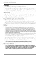
VTrak J830s, J630s Product Manual Warning A Warning notifies you of probable equipment damage or loss of data, or the possibility of physical injury, and how to avoid them. VTrak Overview The Promise VTrak J830s and J630s are optimized for organizations deploying cost-effective small-to-medium application clusters, disk-to-disk backup and midrange storage solutions. Figure 1. VTrak J830s front view Drive Carrier LEDs Drive Carriers Power and Status LEDs Figure 2.
Chapter 1: Introduction to VTrak Figure 3. VTrak J830s rear view I/O Module 1 I/O Module 2 115200 8 N 1 115200 8 N 1 Power Supply 1 Power Supply 2 Figure 4. VTrak J630s rear view I/O Module 1 I/O Module 2 115200 8 N 1 115200 8 N 1 Power Supply 1 Power Supply 2 The two external SAS ports provide the needed connectivity and bandwidth for large capacity solutions requiring multiple JBOD boxes cascaded together while still providing dual server support and host port failover or aggregation.
VTrak J830s, J630s Product Manual Architectural Description The VTrak J830s packs up to 24 drives per system, offering industry-leading capacity in just 4U of standard 19-inch rack space. The VTrak J630s supports up to 16 drives per system, in just 3U of standard 19-inch rack space. The J830s and J630s unit’s compact form factor maximizes density, increasing capacity per unit of rack space.
Chapter 1: Introduction to VTrak Features and Benefits Feature Benefit 4U or 3U 19-inch wide enclosure Installs easily in any standard rackmount. Supports Serial Attached SCSI disk drives Allows you to use the new dual-port SAS disk drives. Supports Serial ATA disk drives Allows you to use your legacy SATA disk drives. Hot-swap feature for drive carriers, Allows a defective component to be I/O modules, and power supplies replaced without interrupting data accessibility to the host system.
VTrak J830s, J630s Product Manual Specifications Drives and Ports Drive Bay Count: J830s, 24 drives. J630s, 16 drives. Supported Disk Drive Interfaces: Serial Attached SCSI (SAS), 6Gb/s and 3Gb/s Serial ATA (SATA), 3Gb/s and 1.5Gb/s External I/O Ports: SAS host port and SAS expansion port.
Chapter 1: Introduction to VTrak Environmental Operating Temperature: 10° to 40°C (10° to 35°C recommended for SAS drives) Non-operating Temperature: -40° to 60°C Operating Humidity: 8% to 80% non-condensing. Non-operating Humidity: 8% to 95% non-condensing Operating Vibration: 0.3g (0 to peak), swept sine, 5 to 500Hz, ½ octave per minute. Non-operating Vibration: 1g (0 to peak), swept sine, 5 to 500Hz, ½ octave per minute. Operating Shock: 5g amplitude, 11ms duration.
VTrak J830s, J630s Product Manual Warranty and Support Warranty: Three years complete system limited warranty. Support: 24x7 email and phone support (English only). 24x7 access to Promise support site to download firmware, utilities, and manuals; to obtain compatibility information and knowledge bulletins. CE Statement Warning: This is a class A product. In a domestic environment this product may cause radio interference in which case the user may be required to take adequate measures.
Chapter 2: Installation • Unpacking the VTrak (below) • Mounting the VTrak in a Rack (page 11) • Installing Disk Drives (page 14) • Making Data Connections (page 19) • Setting Up Serial Cable Connections (page 23) • Connecting the Power (page 24) • Setting Up the CLI Connection (page 26) Please read through these instructions completely before you begin. You might need additional items to complete your installation.
VTrak J830s, J630s Product Manual Notices Warning to User: This is Class A ITE product which might cause radio frequency interference if it is used in a residential environment. In such case, the user would be requested to adopt certain appropriate measures. Figure 1. VTrak J630s front view. The J830s is similar Drive Carrier LEDs Drive Carriers Power and Status LEDs Figure 2. VTrak J630s rear view.
Mounting the VTrak in a Rack Mounting the VTrak in a Rack Cautions • At least two persons are required to safely lift, place, and attach the VTrak unit into a rack system. • Do not lift or move the VTrak unit by the handles, power supplies or the controller units. Hold the subsystem itself. • Do not install the VTrak unit into a rack without rails to support the subsystem. • Only a qualified technician who is familiar with the installation procedure should mount and install the VTrak unit.
VTrak J830s, J630s Product Manual Figure 3. VTrak J630s mounted in a rack with the supplied rails Vertical Rack Post VTrak J630s Attaching screw & flange nut Upper hole only Handles mount outside the rack post Mounting rails (included) mount outside the rack post To install the VTrak subsystem into a rack with the supplied mounting rails: 1. 2. Check the fit of the mounting rails in your rack system. See page 13, Figure 4. Adjust the length of the mounting rails as needed.
Mounting the VTrak in a Rack Figure 4. Rack mount assembly diagram Rack front post Alignment pins two on each flange Rack rear post Rear rail Front rail Support for subsystem Inside of post Rail attaching screws (not included) Inside of post Note that only the front rail has a support for the subsystem.
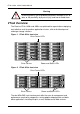
VTrak J830s, J630s Product Manual Installing Disk Drives You can populate the VTrak enclosure with SAS or SATA disk drives. See the Compatibility List on the Promise Website for complete listings of qualified disk drives. For optimal performance, install disk drives of the same model and capacity. Drive Slot Numbering You can install any suitable disk drive into any slot in the enclosure. The diagrams below show how VTrak’s drive slots are numbered. Figure 5.
Installing Disk Drives Installing 3.5-inch Disk Drives Important • If your VTrak has two I/O modules and you are installing SATA disk drives, an AAMUX adapter is required so that both modules can access the SATA disk drive. Obtain AAMUX adapters from Promise Technology, Inc. • Proper installation ensures adequate grounding and minimizes vibration. Always install the disk drives using all four screws. To install your 3.5-inch disk drives: 1. Remove a disk drive carrier. 2.
VTrak J830s, J630s Product Manual Figure 7. Drive carrier with 3.5-inch SATA disk drive and AAMUX SATA Disk Drive AAMUX adapter Disk Drive mounting screw AAMUX mounting screws Disk Drive mounting screw AAMUX mounting screws Figure 8. Drive carrier with 3.
Installing Disk Drives Installing 2.5-inch Disk Drives Cautions • Always use mounting brackets to install 2.5-inch disk drives. Never install disk drives by inserting screws through the bottom of the drive carrier. Obtain mounting brackets and screws from Promise Technology, Inc. • Hold 2.5-inch disk drives by the edge to prevent damage to the drive. • VTrak supports disk drive hot-swapping. To avoid hand contact with an electrical hazard, do not remove more than one drive carrier a time.
VTrak J830s, J630s Product Manual • Install two screws per drive, two screws per bracket, and two screws per adapter. • Snug each screw. Be careful not to over tighten. 5. Reinstall the drive carrier into the VTrak chassis. 6. Repeat steps 2 through 5 until all of your disk drives are installed. Figure 9. 2.5-inch disk drive and mounting bracket Disk drive mounting screws Disk drive Mounting bracket Figure 10.
Making Data Connections Making Data Connections You can configure your VTrak JBOD as: • Basic Direct Attached Storage (DAS) Connection (below) • Cascading DAS Connection (page 20) • Redundant Cascading DAS Connection (page 21) Basic DAS Connection To setup a basic DAS connection: • You must have a SAS HBA card in the Host PC or server. • Connect the SAS HBA card in the Host PC to the SAS IN port (with the circle icon) on the VTrak. See Figure 11.
VTrak J830s, J630s Product Manual Cascading DAS Connection To setup a cascading DAS connection: 1. Connect the SAS HBA card in the Host PC to the SAS IN port (with the circle icon) on the first VTrak. See Figure 12. Use a SFF-8088 4X to 4X external SAS cable (supplied with the VTrak). 2. Connect the SAS OUT port (with the diamond icon) on the same I/O module of the first VTrak to the SAS IN port (with the circle icon) on the second VTrak. Be sure to connect circle icon to diamond icon or vice versa.
Making Data Connections The diagram on page 20 shows the VTrak J630s. Connections with the J830s are exactly the same. This completes data and management connections. Go to “Setting Up Serial Cable Connections” on page 23. Redundant Cascading DAS Connection To setup a redundant cascading DAS connection: 1. Connect the SAS HBA card in the first Host PC to the SAS IN port (with the circle icon) on the first VTrak. See page 22, Figure 13. Use a SFF-8088 4X to 4X external SAS cable (supplied with the VTrak).
VTrak J830s, J630s Product Manual Figure 13.A redundant cascading DAS connection SAS HBA Cards SFF-8088 external 4X to 4X SAS cables SAS OUT diamond port SAS IN circle port 115200 8 N 1 115200 8 N 1 SAS OUT diamond port SAS IN circle port 115200 8 N 1 115200 8 N 1 SAS IN circle port VTrak J630s 115200 8 N 1 115200 8 N 1 VTrak J630s Cascade Configuration 1 Cascade Configuration 2 The diagram above shows the VTrak J630s. A connection with the J830s is exactly the same.
Setting Up Serial Cable Connections Setting Up Serial Cable Connections Serial communication enables the Command Line Interface (CLI) on your PC to monitor and control the VTrak JBOD. The CLI is explained in “Setting Up the CLI Connection” on page 26. The VTrak box includes a RJ11-to-DB9 serial data cable. To set up a serial cable connection: 1. Attach the RJ11 end of the serial data cable to the RJ11 serial connector on the left I/O module on the back of the VTrak. See Figure 14. 2.
VTrak J830s, J630s Product Manual Connecting the Power VTrak ships with clip assemblies to secure the power cords. To secure the power cords: 1. Insert the barbed end of the band into the hole until it snaps into place. 2. Attach the power cord to the power supply. 3. Place the clip over the power cord, slide the clip to the end as shown in the Figure below, then squeeze the clip to tighten it. Figure 15.
Connecting the Power When boot-up is finished and the VTrak subsystem is functioning normally: • Power and Global enclosure status LEDs display green continuously. • I/O module activity LEDs flash green when there is I/O module activity. • System heartbeat LED blinks green once every 4 seconds if one I/O module is installed or once every 2 seconds if two I/O modules are installed. Figure 16.VTrak J630s front panel LED display.
VTrak J830s, J630s Product Manual Setting Up the CLI Connection The VTrak has a Command Line Interface (CLI) to manage all of its functions, including customization. Access the CLI via your PC’s terminal VT100 or ANSI emulation program, such as Microsoft HyperTerminal. The VTrak must be running and the RJ11-to-DB9 serial data cable connected to the primary I/O module and the Host PC or Server’s serial port. See page 23. To set up the CLI connection: 1. 2. 3.
Chapter 3: Management • Front Panel LEDs (below) • Drive Carrier LEDs (page 28) • Power Supply LED (page 29) • I/O Module LEDs (page 30) • Shutting Down and Restarting the VTrak (page 31) • Command Line Interface (page 32) Front Panel LEDs The LEDs on the front panel of the VTrak J830s or J630s unit provide important status information about the subsystem.
VTrak J830s, J630s Product Manual State LEDs Dark Steady Green Flashing Green Amber Red Power System Off Normal — — — Global enclosure status System Off Normal — I/O module No Activity 1 or 2 — Activity — — Heartbeat — Normal* — — System Off Malfunction – Malfunction – one power both power supply supplies * Blinks once every 4 seconds if one I/O module is installed or once every 2 seconds if two I/O modules are installed.
Power Supply LED State LEDs Dark Status Steady Green Flashing Green Steady Blue Flashing Blue HBA/RAID controller determines the LED behavior* Power/Activity** No Drive — Drive Present — Activity * Refer to the user documentation for your HBA or RAID controller for this information. ** Refers to SAS drives or SATA drives with an AAMUX adapter. For SATA drives without an AAMUX adapter, LED behavior depends on the specific disk drive.
VTrak J830s, J630s Product Manual To check a power supply’s installation, follow the same procedure as replacing the power supply, except that you reinstall the original rather than a new one. In most cases, this action fixes a bad connection and allows VTrak to detect the power supply. If this action does not correct the problem, replace the power supply. I/O Module LEDs The LEDs on the VTrak unit’s I/O modules indicate activity on each of its SAS ports and I/O module status. Figure 4.
Shutting Down and Restarting the VTrak Shutting Down and Restarting the VTrak To shutdown the VTrak, turn OFF the switches on both power supplies. Figure 5. Power switches on VTrak J630s. The J830s is similar Power switch 115200 8 N 1 Power switch 115200 8 N 1 Power Supply 2 Power Supply 1 To restart the VTrak, wait at least 30 seconds after shutdown, then turn ON the switches on both power supplies.
VTrak J830s, J630s Product Manual Command Line Interface • Command Set (page 32) • Enclosure Command (page 32) • Making Enclosure Settings (page 35) • Factorydefaults Command (page 37) • Help Command (page 37) • Link Command (page 38) • Route Command (page 41) • Uptime Command (page 42) • ? Command (page 42) Command Set The CLI uses the following set of commands: enclosure – Displays enclosure settings and component information.
Command Line Interface Viewing Enclosure Information To view enclosure information: At the cli> prompt, type enclosure and press Enter. cli>enclosure The system returns: ------------------------------------------------------------------Time Since Power Up : 1 day 9 hours 46 minutes 36 seconds Enclosure : SBB SAS 6G JBOD 3U-16 Bay Serial Number : S987123 I/O Module ID : 1 Max I/O Module Cnt : 2 Firmware Version : 6.04.0000.
VTrak J830s, J630s Product Manual 5 I/O Module2 0.93V 6 I/O Module2 3.
Command Line Interface Making Enclosure Settings The Enclosure command also enables you to make settings: • Viewing Current Settings (page 35) • Setting Temperature Thresholds (page 35) • Setting Thermal Management (page 36) • Setting Shutdown (page 36) • Setting Minimum Fan Speed (page 36) Viewing Current Settings To view current enclosure settings: 1. 2. At the cli> prompt, type enclosure and press Enter.
VTrak J830s, J630s Product Manual Setting Thermal Management Thermal Management monitors enclosure and I/O module temperature and adjusts fan speeds for proper cooling. Promise recommends that you set Thermal Management to enabled. To enable Thermal Management: At the cli> prompt, type enclosure -a mod -s "thermalmanager=1" and press Enter. For this command, 1 enables and 0 disables.
Command Line Interface Factorydefaults Command Caution Restoring default settings can disrupt your VTrak’s function. Use this feature only when necessary. To reset all subsystem settings to their factory default values: 1. At the cli> prompt, type factorydefaults and press Enter. cli>factorydefaults The system returns: Do you wish to proceed restoring factory default? (y/n): 2. At the (y/n) prompt, type y and press Enter.
VTrak J830s, J630s Product Manual Link Command The Link command displays information about SAS data links, including: • Viewing Link Status (page 38) • Viewing Link Statistics (page 39) • Clearing the Error Count (page 41) Viewing Link Status To view link status: At the cli> prompt, type link and press Enter.
Command Line Interface 27 CN#1 SAS 28 CN#2 SAS 29 CN#2 SAS 30 CN#2 SAS 31 CN#2 SAS Phy : PHY ID Rate: Rate 1.5G/3G/6G Link: Link Connected 6.0G OK 6.0G OK 6.0G OK 6.0G OK 6.0G OK Port: Port Type Init: Init Passed PRdy: Phy Ready End End End End End ---Rdy ---Rdy ---Rdy ---Rdy ---Rdy Type: SAS or SATA Dev : Device Type The following items are reported in the table above: • Phy number – Links are individual Phys, numbered 0 through 31 on J830s units, and 0 through 23 on J630s units.
VTrak J830s, J630s Product Manual 13 14 15 16 17 18 19 20 21 22 23 24 25 26 27 28 29 30 31 InDW: DwLo: CoVi: Slot14 --------- --------- --------- --------- --------Slot15 --------- --------- --------- --------- --------Slot16 --------- --------- --------- --------- --------Slot17 --------- --------- --------- --------- --------Slot18 --------- --------- --------- --------- --------Slot19 --------- --------- --------- --------- --------Slot20 --------- --------- --------- --------- --------Slot21 ---------
Command Line Interface Clearing the Error Count To clear all link error counts: At the cli> prompt, type link -a clear and press Enter. cli>link -a clear To clear the link error count for a specific Phy: At the cli> prompt, type link -a clear -p and press Enter. cli>link -a clear -p 1 Route Command To view the SAS addresses of the devices in your domain: At the cli> prompt, type route and press Enter.
VTrak J830s, J630s Product Manual The route command displays SAS addresses that are attached to the SAS ports of the VTrak unit. Three items are reported: • Index – Arbitrary numbers, listed in numerical sequence. • SAS Address – SAS address of the drive or component. • CN# – Downstream SAS port connector number. See page 21 for a diagram of connectors on the I/O module. • Phy number – Links are individual Phys, numbered 0 through 31 on J830s units, and 0 through 23 on J630s units.
Chapter 4: Support This chapter covers the following topics: • Frequently Asked Questions (below) • Contacting Technical Support (page 44) • Limited Warranty (page 47) • Returning the Product For Repair (page 49) Frequently Asked Questions What kind of disk drives can I use with VTrak? VTrak supports 2.5-inch and 3.5-inch SAS and SATA disk drives. See the Compatibility List on the Promise Website for a list of qualified disk drives.
VTrak J830s, J630s Product Manual Can I hot-swap a failed drive with a new one? Yes. Disk drives are hot-swappable on the VTrak unit. Can the VTrak run using just one power supply? Yes, it is possible to run the VTrak unit on a single power supply. However, leaving one power supply off means there is no redundancy if the remaining power supply fails. And it reduces air flow through the enclosure, which can contribute to overheating. Always switch on both power supplies.
Chapter 4: Support The Netherlands E-mail Support e-Support On-Line Fax Support +31 0 40 256 9463 Attn: Technical Support Phone Support +31 0 40 235 2600 If you wish to write us for support: Promise Technology Europe B.V.
VTrak J830s, J630s Product Manual Taiwan E-mail Support e-Support On-Line Fax Support +886 3 578 2390 Attn: Technical Support Phone Support +886 3 578 2395 ext. 8822 or 8823 If you wish to write us for support: Promise Technology, Inc. 2F, No. 30, Industry E. Rd. IX Science-based Industrial Park Hsin-Chu 30075, Taiwan (R.O.C.
Chapter 4: Support Limited Warranty Promise Technology, Inc. (“Promise”) warrants that this product, from the time of the delivery of the product to the original end user: a) all components for a period of three (3) years; b) will conform to Promise’s specifications; c) will be free from defects in material and workmanship under normal use and service.
VTrak J830s, J630s Product Manual back up or otherwise save important data before installing any product and continue to back up your important data regularly. No other document, statement or representation may be relied on to vary the terms of this limited warranty. Promise’s sole responsibility with respect to any product is to do one of the following: a) replace the product with a conforming unit of the same or superior product; b) repair the product.
Chapter 4: Support Returning the Product For Repair If you suspect a product is not working properly, or if you have any questions about your product, contact our Technical Support Staff through one of our Technical Services, making sure to provide the following information: • Product model and serial number (required) • Return shipping address • Daytime phone number • Description of the problem • Copy of the original purchase invoice The technician will assist you in determining whether the prod
VTrak J830s, J630s Product Manual You are responsible for the cost of insurance and shipment of the product to Promise. Note that damage incurred due to improper transport or packaging is not covered under the Limited Warranty. When repairing returned product(s), Promise may replace defective parts with new or reconditioned parts, or replace the entire unit with a new or reconditioned unit.
Appendix A: Miscellaneous • Adding a Second I/O Module (below) • Replacing a Power Supply Fan (page 52) Adding a Second I/O Module Warning The electronic components within the VTrak are sensitive to damage from Electro-Static Discharge (ESD). Observe appropriate precautions at all times when handling the VTrak or its subassemblies. The VTrak J830s and J630s units ship with one or two I/O modules. If your VTrak came with only one I/O module, you can upgrade by installing a second I/O module.
VTrak J830s, J630s Product Manual The system returns: ------------------------------------------------------------------Time Since Power Up : 0 days 0 hours 1 minute 45 seconds Enclosure : SBB SAS 6G JBOD 3U-16 Bay Serial Number : S987123 I/O Module ID : 2 Max I/O Module Cnt : 2 Firmware Version : 6.04.0000.
Replacing a Power Supply Fan Removing the Fan Assembly To remove the power supply fan assembly: 1. Shut off the power supply at the switch and unplug the power cord. 2. Loosen the mounting screws, pull the power supply out of the VTrak enclosure, and place the power supply on a static-free surface. 3. Remove the screws holding the fan assembly in place. There are five screws: two on top, two on the bottom, and one on the side. See Figure 1. Figure 1.
VTrak J830s, J630s Product Manual 4. Pull the fan assembly out of the power supply. See Figure 2. Figure 2.
Replacing a Power Supply Fan Installing the Fan Assembly To install the power supply fan assembly: 1. Insert the new fan assembly into the power supply. Be sure the tab passes through the locator hole. See Figure 3. Figure 3. Tab in locator hole 2. Install the five screws that hold the fan assembly in place. See page 53, Figure 1. 3. Put the power supply back into the VTrak enclosure and tighten the mounting screws. 4. Plug in the power cord and turn on the power supply at the switch.
VTrak J830s, J630s Product Manual 56
Index device type 39 disk drives hot-swappable 44 install 14 LEDs 25, 28 numbering 14 supported 43 disparity error count 40 drive type 39 Symbols ? command 42 A AAMUX adapter 15, about this manual 1 17, 28, 43 B BTUs/hour 6 E C enclosure command 32, 43 global status LED 25, 27 information 33 reboot 31 settings 35 shutdown 31 error counts 40 ESD Warning 9, 51, 52 cable RJ11-to-DB9 9, 23, 26 SAS SFF-8088 9, 20, 21 CE statement 8 clear link error count 41 clips, power cord 24 code violation count 40
VTrak J830s, J630s Product Manual I P I/O module activity LED 25, 27 add second module 51 role (primary/secondary) phy change count 40 number 39, 40 ready status 39 reset problem count 40 port number 39, 40 power connection 24 consumption 6 LED 25, 27 power cord clips 24 power supply LED 29 redundancy 44 status 29, 33 power supply fan install 55 remove 53 32, 33, 43, 52 status LED 30 invalid D-word count IRAM statement 8 40 L LEDs disk drive 25, 28 drive carrier 28 enclosure global status 25, front
Index serial number, view 33 setting minimum fan speed 36 shutdown 36 temperature 35 thermal management 36 SFF-8088 cable 9, 20, 21 shutdown setting 36 slot number 39, 40 Specifications 6 status disk drive 28 enclosure global 27, 28 I/O module 30 phy 39 power supplies 29, 33 temperatures 33 voltage 33 subsystem reboot 31 shutdown 31 System heartbeat LED 25, 27 system temperatures 33 U uptime command 42 V view enclosure settings 35 firmware version 33 I/O module role 33 link status and statistics 38 powe
VTrak J830s, J630s Product Manual 60