VTRAK M310p, M210p PRODUCT MANUAL Version 1.
VTrak M310p, M210p Product Manual Copyright © 2006 Promise Technology, Inc. All Rights Reserved. Copyright by Promise Technology, Inc. (Promise Technology). No part of this manual may be reproduced or transmitted in any form without the expressed, written permission of Promise Technology. Trademarks Promise, and the Promise logo are registered in U.S. Patent and Trademark Office. All other product names mentioned herein may be trademarks or registered trademarks of their respective companies.
Contents Chapter 1: Introduction . . . . . . . . . . . . . . . . . . . . . . . . . . . . . . . . . . . . .1 About This Manual . . . . . . . . . . . . . . . . . . . . . . . . . . . . . . . . . . . . . . .1 Overview . . . . . . . . . . . . . . . . . . . . . . . . . . . . . . . . . . . . . . . . . . . . . .2 Architectural Description . . . . . . . . . . . . . . . . . . . . . . . . . . . . . . . . . .3 Features and Benefits . . . . . . . . . . . . . . . . . . . . . . . . . . . . . . . . . . .3 Specifications .
VTrak M310p, M210p Product Manual Chapter 4: Management with WebPAM PROe, continued Event Frame . . . . . . . . . . . . . . . . . . . . . . . . . . . . . . . . . . . . . . .47 Subsystems . . . . . . . . . . . . . . . . . . . . . . . . . . . . . . . . . . . . . . . . . . .47 Subsystem . . . . . . . . . . . . . . . . . . . . . . . . . . . . . . . . . . . . . . . .48 Administrative Tools . . . . . . . . . . . . . . . . . . . . . . . . . . . . . . . . . . . .54 User Management . . . . . . . . . . . . . . . . .
Contents Chapter 5: Management with the CLU, continued Exit the CLU . . . . . . . . . . . . . . . . . . . . . . . . . . . . . . . . . . . . . .124 CLU Function Map . . . . . . . . . . . . . . . . . . . . . . . . . . . . . . . . . . . . .125 Quick Setup . . . . . . . . . . . . . . . . . . . . . . . . . . . . . . . . . . . . . . . . . .132 Subsystem Management . . . . . . . . . . . . . . . . . . . . . . . . . . . . . . . .132 Alias . . . . . . . . . . . . . . . . . . . . . . . . . . . . . . . . . . . . . . .
VTrak M310p, M210p Product Manual Chapter 5: Management with the CLU, continued Background Activities List . . . . . . . . . . . . . . . . . . . . . . . . . . . .153 Event Viewer . . . . . . . . . . . . . . . . . . . . . . . . . . . . . . . . . . . . . . . . .154 Runtime Events . . . . . . . . . . . . . . . . . . . . . . . . . . . . . . . . . . . .154 NVRAM Events . . . . . . . . . . . . . . . . . . . . . . . . . . . . . . . . . . . .154 Additional Info and Management . . . . . . . . . . . . . . . . . . .
Contents Chapter 7: Technology Background, continued Predictive Data Migration (PDM) . . . . . . . . . . . . . . . . . . . . . . . . . .199 PDM Triggers . . . . . . . . . . . . . . . . . . . . . . . . . . . . . . . . . . . . .199 Transition . . . . . . . . . . . . . . . . . . . . . . . . . . . . . . . . . . . . . . . . . . . .200 Example . . . . . . . . . . . . . . . . . . . . . . . . . . . . . . . . . . . . . . . . .200 Chapter 8: Troubleshooting . . . . . . . . . . . . . . . . . . . . . . . . . . . . . .
VTrak M310p, M210p Product Manual viii
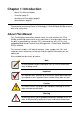
Chapter 1: Introduction • About This Manual (below) • Overview (page 2) • Architectural Description (page 3) • Specifications (page 5) Thank you for purchasing Promise Technology’s VTrak M310p or M210p external disk array subsystem. About This Manual This Product Manual describes how to setup, use, and maintain the VTrak M310p and M210p external disk array subsystem.
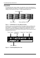
VTrak M310p, M210p Product Manual Overview VTrak provides data storage solutions for applications where high performance and data protection are required. The failure of any single drive will not affect data integrity or accessibility of the data in a RAID protected logical drive. Drive Carrier LEDs Drive Carriers Power and Status LEDs Figure 1. VTrak M310p front view (M210p is similar) A defective drive may be replaced without interruption of data availability to the host computer.
Chapter 1: Introduction Architectural Description The VTrak M310p and M210p are Direct Attached Storage (DAS) subsystems. The subsystems support 1.5 Gb/s and 3.0 Gb/s SATA disk drives: • VTrak M310p supports up to 12 disk drives in a 2U enclosure • VTrak M210p supports up to 8 disk drives in a 2U enclosure All M310p and M210p enclosures include a mid-plane, RAID controller, power and cooling units, and enclosure processor all in one cable-less chassis design.
VTrak M310p, M210p Product Manual Feature Benefit Tagged Command Queuing (TCQ) Maximum performance in Multi-Threaded up to 128 commands Operating Systems. Supports SATA II Native Command High performance and efficiency through Queuing efficient command re-ordering. Supports DDF compliant metadata Enabled disk array migration from one on disk controller to another.
Chapter 1: Introduction Feature Benefit Command-line and Graphic-user interfaces Choice of control and monitoring methods for greater flexibility. Specifications Drive Capacity (M310p): 12 SATA disk drives (3.5" x 1" form factor only). Drive Capacity (M210p): 8 SATA disk drives (3.5" x 1" form factor only).
VTrak M310p, M210p Product Manual Power Supply: Dual power supplies. M310p, 360W. M201p, 260W. 100–240 VAC auto-ranging, 50–60 Hz, dual hot-swap and redundant with PFC, N+1 design Operating Temperature: 41° to 104°F (5° to 40°C) Non-operational Temperature: -40° to 140°F (-40° to 60°C) Relative Humidity: Maximum 90% Vibration: Random, 0.
Chapter 2: Installation • Unpack the VTrak storage subsystem (below) • Mount VTrak in a Rack (page 8) • Install Disk Drives (page 10) • Connect Network and Data Cables (page 13) • Set Up Serial Cable Connections (page 14) • Connect the Power (page 15) Unpack the VTrak The VTrak box contains the following items: • VTrak Unit • Quick Start Guide • Null Modem Cable • 1.
VTrak M310p, M210p Product Manual Mount VTrak in a Rack VTrak M310p Vertical Rack Post Handles mount outside the rack post Mounting rails (included) mount inside the rack post Figure 1. Rackmounted VTrak M310p (M210p is similar) The VTrak M310p or M210p installs to the rack using the supplied mounting rails. You can also use your existing rails.
Chapter 2: Installation Cautions • At least two persons are required to safely lift, place, and attach the VTrak enclosure into a rack system. • Do not lift or move the VTrak enclosure by the handles, power supplies or the controller units. Hold the enclosure itself. • Do not install the VTrak enclosure into a rack without rails to support the enclosure. To install the VTrak enclosure into a rack with the supplied mounting rails (see Figure 2): 1.
VTrak M310p, M210p Product Manual Install Disk Drives You can populate the VTrak with 1.5 GB and 3.0 GB SATA drives. • VTrak M310p supports up to 12 disk drives • VTrak M210p supports up to 8 disk drives All VTrak M310p or M210p models provide the RAID configurations listed below. See Chapter 7, page 179 for a complete explanation of RAID on VTrak.
Chapter 2: Installation Counter-sink screws only. WARNING: SATA Drive Mounting Holes SATA Drive Mounting Holes Figure 3. VTrak M310p/M210p drive carrier mounting holes Serial ATA Disk Drive Figure 4. SATA Disk Drives mount at the front of the carrier 1. Carefully lay the drive into the drive carrier at the front, so that the screw holes on the bottom line up. 2. Insert the screws through the holes in the drive carrier and into the bottom of the disk drive (see Figure 3). 3.
VTrak M310p, M210p Product Manual 4. Repeat these steps until all of your disk drives are installed. Caution If you plan to operate your VTrak with fewer than a full load of disk drives, install all of the drive carriers into the enclosure, to ensure proper airflow for cooling. Important Be sure each drive is securely fastened to its carrier. Proper installation ensures adequate grounding and minimizes vibration. Do not install drives with fewer than four screws.
Chapter 2: Installation Connect Network and Data Cables Network Switch Management Port O O I I CONSOLE In Mgmt In Out Out VTrak In connector SCSI Channel (1 of 2) NIC SCSI HBA Card PC/Server Figure 8. VTrak M310p/M210p DAS connections This arrangement requires: • A network switch • A network interface card (NIC) in the PC • A SCSI HBA card in the PC • A SCSI cable that fits your HBA card and has a VHDCI connector to fit the VTrak SCSI channel VTrak’s SCSI connectors are bi-directional.
VTrak M310p, M210p Product Manual Set Up Serial Cable Connections The RS-232 Serial connection enables the Command Line Utility (CLU) on your PC to monitor and control VTrak. DB-9 Serial Connector CONSOLE O Mgmt O I I CONSOLE Mgmt Figure 9.
Chapter 2: Installation Connect the Power Plug the power cords and switch on both power supplies on. When the power is switched on, the LEDs on the front of the VTrak will light up. Power FRU Status Logical Drive Status RAID Controller Activity Reserved Controller Heartbeat Figure 10.
VTrak M310p, M210p Product Manual If there is no disk drive in the carrier, the Disk Status LED and the Power/Activity LED will remain dark. When you first power-up the VTrak, the audible alarm beeps twice to show normal operation. Go to “Chapter 3: Setup” on page 17.
Chapter 3: Setup • VTrak Setup with CLI or CLU (below) • VTrak Setup with WebPAM PROe (page 22) VTrak Setup with CLI or CLU After installation, the next step is to configure VTrak. To set date, time and IP addresses, you must use the Command Line Interface (CLI) or the Command Line Utility (CLU). For disk array creation, you can use the CLI, CLU or WebPAM PROe. This Chapter only deals with basic functions needed to setup a new VTrak.
VTrak M310p, M210p Product Manual CLI 1. Type the following string to set the Date and Time, then press Enter administrator@cli> date -a mod -d 2006/06/15 -t 16:45:00 Type the date in yyyy/mm/dd format and the time in hh/mm/ss format with a 24-hour clock. In the above example, the date was June 15, 2006. The time was 4:45 pm. Your values will be different. 2. Type the following string to set the Management Port IP address and other settings, then press Enter.
Chapter 3: Setup CLU 1. At the admin@cli prompt, type menu and press Enter. The CLU main menu appears. 2. With Quick Setup highlighted, press Enter. The first Quick Setup screen enables you to make Date and Time settings. System Date and Time 1. Press the arrow keys to highlight System Date. 2. Press the backspace key to erase the current date. 3. Type the new date. 4. Follow the same procedure to set the System Time.
VTrak M310p, M210p Product Manual 5. Press Ctrl-A to save these settings and move to the Management Port configuration screen. Management Port By default, DHCP is enabled on VTrak (above). To set Management Port settings manually, or to view the current settings, you must disable DHCP. To view the current Management Port settings: 1. Press the arrow keys to highlight DHCP. 2. Press the spacebar to toggle to Disabled. The current Management Port IP are displayed (above). 3.
Chapter 3: Setup 5. Press Ctrl-A to save these settings and move to the RAID configuration screen. To make Management Port settings manually: 1. Press the arrow keys to highlight DHCP. 2. Press the spacebar to toggle to Disabled. 3. Press the arrow keys to highlight IP Address. 4. Press the backspace key to erase the current IP Address. 5. Type the new IP Address. 6. Follow the same procedure to specify the Subnet Mask, Gateway IP Address and DNS Server IP Address.
VTrak M310p, M210p Product Manual VTrak Setup with WebPAM PROe Notes • You can also use the CLU to create disk arrays and logical drives. See “Chapter 5: Management with the CLU” on page 119 for more information. • The WebPAM PROe software is embedded on the VTrak M310p or M210p subsystem. No installation is required.
Chapter 3: Setup Note Whether you select a regular or a secure connection, your login to WebPAM PROe and your user password are always secure. . 3. When the opening screen appears, type administrator in the User Name field and type password in the Password field. The User Name and Password are case sensitive. 4. Click the Login button. After sign-in, the WebPAM PROe opening screen appears (next page).
VTrak M310p, M210p Product Manual Note Make a Bookmark (Netscape Navigator) or set a Favorite (Internet Explorer) of the Login Screen so you can access it easily next time. The first time you log in to WebPAM, there will be no Users except for “administrator”. There will be no disk arrays or logical drives.
Chapter 3: Setup Logged-in User Subsystem (IP address) Administration Tools User Management Network Management SCSI Management Storage Services Software Management Controller Group Enclosure Group Disk Array Group Spare Drive Group Logical Drive Summary Use the Tree to navigate to the various functions of WebPAM PROe. Click on an item in the Tree to display it in the window.
VTrak M310p, M210p Product Manual Create a Disk Array Click on the Disk Arrays icon. The Array Configuration menu appears. Since this VTrak is newly activated, there are no disk arrays or logical drives yet. There are three options: Automatic, Express and Advanced. Select one and click the Next button. Or select one from the dropdown menu on the Create tab. Automatic The Disk Array Automatic Creation option enables you to create a new disk array following a default set of parameters.
Chapter 3: Setup • Disk Arrays – The number of physical drives in the disk array, their ID numbers, configurable capacity and the number of logical drives to be created • Logical Drives – The ID number of the logical drive(s), their RAID level, capacity and stripe size • Spare Drives – The physical drive ID number of the dedicated hot spare assigned to this disk array If you accept these parameters, click the Submit button. The new disk array appears in the Disk Array List on the Information tab.
VTrak M310p, M210p Product Manual Follow these steps to create a new disk array. 1. 2. Check the boxes to select any one or a combination of: • Redundancy – The array will remain available if a physical drive fails • Capacity – The greatest possible amount of data capacity • Performance – The highest possible read/write speed • Spare Drive – A hot spare drive In the Number of Logical Drives field, enter the number of logical drives you want to make from this disk array.
Chapter 3: Setup 4. • Transaction Log • Other Click the Update button. Or check the Automatic Update box and updates will occur automatically.
VTrak M310p, M210p Product Manual If you are uncertain about choosing parameters for your disk array, use the Express or Automatic option to create your disk array. To create a new disk array: 1. Enter a name for the disk array in the field provided. 2. Check the box to enable the following features. 3. • Media Patrol – A routine maintenance procedure that checks the magnetic media on each disk drive.
Chapter 3: Setup On this screen you will specify your logical drives. Specify one logical drive at a time until the full capacity of the disk array is allocated. 5. Enter an Alias (name) for the first logical drive. 6. Choose a RAID level from the dropdown menu. The choice of RAID levels depends on the number of physical drives you selected. 7. Specify a Capacity and the unit of measure (MB, GB, TB). This value will be the data capacity of the logical drive.
VTrak M310p, M210p Product Manual 10. Choose a Read Cache policy: • ReadCache • ReadAhead • No Cache 11. Choose a Write Cache policy: • WriteThru • WriteBack 12. Click the Update button. When you click the Update button, WebPAM PROe sets up one logical drive and adds it to the New Logical Drive lists at the bottom of the window. To create another logical drive, repeat steps 5 through 12, above.
Chapter 3: Setup If you want to change a logical drive setting, click on the logical drive at the bottom of the window. The entry and the capacity usage are highlighted. Make your changes to the parameters and click the Update button.
VTrak M310p, M210p Product Manual 13. When you have finished specifying logical drives, click the Next button. The proposed disk array appears with the logical drive(s) you specified.
Chapter 3: Setup 14. If you agree with the proposed disk array and logical drive(s), click the Submit button. If you disagree, click the Back button and make changes as needed. Additional Logical Drives If you want to create additional logical drives and there is unused space on the current disk array, click on the Disk Array icon and click on the Create LD tab. You will go to Disk Array Advanced Creation (see page 29).
VTrak M310p, M210p Product Manual 36
Chapter 4: Management with WebPAM PROe • VTrak Status Indicators (below) • Controllers (page 77) • Drive Status Indicators (page 39) • Enclosures (page 81) • Audible Alarm (page 39) • Physical Drives (page 86) • Log-in/Log-out (page 40) • Disk Arrays (page 91) • Graphic User Interface (page 43) • Logical Drives (page 104) • Subsystems (page 47) • Spare Drives (page 112) • Administrative Tools (page 54) This chapter describes using embedded WebPAM PROe to monitor and manage your RAI
VTrak M310p, M210p Product Manual When boot-up is finished and the VTrak is functioning normally: • Controller Heartbeat LED blinks green seven times in three seconds, goes dark for six seconds, then repeats the blink pattern. • Power, FRU and Logical Drive LEDs display green continuously. • The RAID Controller LED flashes green if there is activity on the controller. See the table below.
Chapter 4: Management with WebPAM PROe Drive Status Indicators There are two LEDs on each Drive Carrier. They report the presence of power and a disk drive, and the current condition of the drive. Disk Status Power/Activity Figure 2. VTrak M310p/M210p disk carrier LEDs The VTrak spins up the disk drives sequentially in order to equalize power draw during start-up. After a few moments the Power/Activity and Disk Status LEDs should display green.
VTrak M310p, M210p Product Manual When you first power-up the VTrak, it beeps twice to show normal operation. The audible alarm sounds at other times to inform you that the VTrak needs attention. But the alarm does not specify the condition. When the alarm sounds: • Check the front and back of VTrak for red or amber LEDs, as described above. • If email notification is enabled, check for new messages. • Check for yellow !s • Check the event log (see page 49). red Xs in Tree View (see page 46).
Chapter 4: Management with WebPAM PROe .When the opening screen appears, type administrator in the User Name field and type password in the Password field. The User Name and Password are case sensitive. 3. Click the Login button.
VTrak M310p, M210p Product Manual After sign-in, the WebPAM PROe opening screen appears. Figure 4. WebPAM PROe Opening Screen The first time you log in to WebPAM PROe, there will be no Users except for “administrator”. There will be no disk arrays or logical drives. If you setup your VTrak using WebPAM PROe (see “Chapter 3: Setup” on page 17) you will have one User, “administrator” and one disk array and logical drive.
Chapter 4: Management with WebPAM PROe Graphic User Interface • Header (page 44) • Management Window (page 47) • Tree View (page 46) • Event Frame (page 47) VTrak features a browser-based, graphic user interface. Your Internet browser is the basic component to access VTrak from your PC.
VTrak M310p, M210p Product Manual Item Function Header Enables you to make a language selection, show or hide the event frame, show or hide network storage subsystems, display contact information, log out, and display the Help directory. Tree View Navigates around all components of the Subsystem, including SCSI management, network and service management, RAID controller, enclosure, physical drives, disk arrays, logical drives, and spare drives.
Chapter 4: Management with WebPAM PROe 3. Click View again to hide the Event Frame. Storage Network The VTrak graphic user interface can currently display in Storage Network in the Tree View. The Storage Network consists of all the VTrak subsystem enclosures currently accessible on the network. When you log into a VTrak, that VTrak subsystem is the only one to display in the Subsystems list. To view the Storage Network: 1. 2. Click on Storage Network in the Header.
VTrak M310p, M210p Product Manual Tree View Below are the components of Tree View.
Chapter 4: Management with WebPAM PROe Management Window The Management Window provides the actual user interface with the VTrak. This window changes depending on which item you select in Tree View and which tab you select in the Management Window itself. Event Frame To display the Event Frame, click on View in the Header, then click on Show Event Frame.
VTrak M310p, M210p Product Manual Subsystem VTrak subsystems are identified in the Tree by their Management Port IP address. Click on the Subsystem icon in Tree View, then on the individual tabs in Management View to access the functions. Subsystem Information The Subsystem–Information tab provides information about a specific subsystem. To set an alias for this subsystem, click the Settings tab. To review the event log, click the Event tab.
Chapter 4: Management with WebPAM PROe Subsystem Events The Subsystem–Event tab provides information from the event (log) file of a specific subsystem. Events are listed and sorted by: • Number – A consecutive decimal number assigned to a specific event • Device – Battery, controller, logical drive, physical drive, port, etc. • Event ID – The hexadecimal number that identifies the specific type of event • Severity – Information, Warning, Minor, Major, Critical, and Fatal.
VTrak M310p, M210p Product Manual 4. In the File Download Security Warning box, click the Save button. 5. In the Save As dialog box, navigate to the directory where you want to save the event file. 6. Enter a name for the event file (“eventlog” is the default file name). 7. Click the Save button. Background Activities The Subsystem–Background Activities tab provides information about functions that runs in the background on your subsystem: • Disk Array Rebuilding.
Chapter 4: Management with WebPAM PROe 5. • Medium allocates a balance of system resources to the function and data read/write operations. • High allocates more system resources to the function and fewer to data read/write operations. Set the Reassigned Block threshold. When an error occurs in a physical drive, the directions to the block containing error are reassigned. When the number of reassigned blocks exceeds the threshold, PDM is triggered. 6. Set the Error Block threshold.
VTrak M310p, M210p Product Manual 3. Click on the Scheduler tab dropdown menu and select an item (see the list above). 4. In the Scheduler dialog box, check the Enable This Schedule box. 5. Select a start time (24-hour clock). 6. Select a Recurrence Pattern. • Daily – Enter the number of days between events. • Weekly – Enter the number of weeks between events and select which days of the week. • Monthly – Select a calendar day of the month (1 – 31).
Chapter 4: Management with WebPAM PROe 5. Click the Submit button. Lock The Subsystem–Lock tab displays lock status and enables you to lock or unlock a subsystem controller. The lock prevents other sessions (including by the same user) from making a configuration change to the controller until the lock expires or a forced unlock is done. When the user who locked the controller logs out, the lock is automatically released. You can set the lock to last from one minute to one day.
VTrak M310p, M210p Product Manual 5. Click the Submit button. Release Lock To release the lock for this subsystem: 1. Click on the Subsystem icon Tree View. 2. Click on the Lock tab in Management View. If you are the User who set the lock, click on the Unlock option. If another User set the lock and you are a Super User, click on the Unlock option and check the Force Unlock box. 3. Click the Submit button.
Chapter 4: Management with WebPAM PROe User Management User Management includes all functions dealing with user accounts. User Information The User Management–Information tab lists the user, his/her status, access privileges, display name, and email address. To access this tab: 1. Click the Subsystem icon in Tree View. 2. Click the Administrative Tools 3. Click on the User Management icon. icon. To add a user, log in as a Super User, then click the Create tab in Management View.
VTrak M310p, M210p Product Manual User Settings – User The User Management–Settings tab enables a user to view and change his/her display name and email address. To change user settings: 1. Click the Subsystem icon in Tree View. 2. Click the Administrative Tools 3. Click on the User Management 4. Click on the Settings tab in Management View. 5. Enter or change the display name or mail address. 6. Click the Submit button. icon. icon.
Chapter 4: Management with WebPAM PROe For VTrak’s Email settings, see “Email” on page 64.
VTrak M310p, M210p Product Manual User Password – Administrator The Administrator or a Super User can change another user’s password. To make these changes: 1. Click the Subsystem icon in Tree View. 2. Click the Administrative Tools 3. Click on the User Management 4. In the list of users, click on the link of the user whose settings you want to change. icon. icon. The Settings screen for the selected user displays. 5. Click on the Password tab in Management View. 6.
Chapter 4: Management with WebPAM PROe 6. Enter a password for this user in the New Password and Retype Password fields. A password is optional. If you do not assign password, tell this user to leave the password field blank when he/she logs into to WebPAM PROe. The user can create his/her own password, see “User Password – Users” on page 58. 7. Check the Enabled box to enable this user on this subsystem. 8. Enter a display name in the Display Name field. A display name is optional but recommended.
VTrak M310p, M210p Product Manual 4. Click on the Delete tab in Management View. 5. Check the box to the left of the user you want to delete. 6. Click the Submit button. 7. Click OK in the confirmation box. Note There will always be at least one Super User account. A Super User cannot delete his/her own account.
Chapter 4: Management with WebPAM PROe Network Management Network Management deals with network connections to the VTrak’s Management Port.
VTrak M310p, M210p Product Manual SCSI Management SCSI Channel Information 1. Click the Subsystem icon in Tree View. 2. Click the Administrative Tools 3. Click on the SCSI Management icon. icon. The Channel tab displays SCSI Channel Information: • Maximum Data Transfer Rate • Termination Status • List of currently enabled targets To see Target information, click the Target tab. SCSI Channel Settings 1. Click the Subsystem 2. Click the Administrative Tools 3. icon in Tree View. icon.
Chapter 4: Management with WebPAM PROe Cautions • Turn off termination only when the VTrak is NOT the last device in the SCSI chain. • Internal termination only works on the “Out” SCSI connectors. SCSI Target Information 1. Click the Subsystem 2. Click the Administrative Tools 3. icon in Tree View. icon. Click on the SCSI Management icon. The Channel tab displays SCSI Channel Information: 4. Click on the Target tab.
VTrak M310p, M210p Product Manual Edit a LUN Map Important You must enable a Target before you assign a LUN to it. See “SCSI Channel Settings” on page 62. 1. Click on the Subsystem icon in Tree view. 2. Click on the Administrative Tools 3. Click on the Storage Services 4. Click the LUN Map tab in Management View. 5. From the LUN Map tab dropdown menu, select Edit LUN Map. 6. Select Port 1 or Port 2 from the Port ID dropdown menu. 7.
Chapter 4: Management with WebPAM PROe 1. Click the Subsystem icon in Tree View. 2. Click the Administrative Tools icon. 3. Click on the Email Setting link. 4. Enter the IP address for your SMTP server. 5. Enter server port number for your SMTP server. 25 is the default. 6. Select Yes to enable SMTP authentication or No to disable. 7. If you selected Yes for SMTP authentication, enter a Username and Password in the fields provided. 8.
VTrak M310p, M210p Product Manual • If the service is stopped, click the Start button to start the service. • If the service is started, click the Stop button to stop the service. Or click on the Restart button to restart the service. SLP VTrak’s SLP service discovers services available over the Internet. To change the SLP startup settings: 1. Click the Subsystem icon in Tree View. 2. Click the Administrative Tools 3. Click on the SLP Setting link. 4. Under Startup Type: 5. icon.
Chapter 4: Management with WebPAM PROe 5. Enter Session Time Out interval. 24 minutes is the default. 6. If you want to use a secure connection, check the Enable SSL box. 7. If you checked the Enable SSL box, enter a HTTPS Port number. 443 is the default. 8. If you want to download a SSL Certificate, check the Download Certificate box. 9. If you checked the Download Certificate box, enter the Certificate filename or click on the Browse... button to locate it. 10.
VTrak M310p, M210p Product Manual To change the Telnet settings: 1. Click the Subsystem icon in Tree View. 2. Click the Administrative Tools 3. Click on the Telnet Setting link. 4. Enter the Telnet Port number. icon. 2300 is the default. 5. Enter the Maximum Number of Connections. 4 is the default. 6. Enter the Session Time Out interval. 24 minutes is the default. 7. When you are done, click on the Submit button. 8.
Chapter 4: Management with WebPAM PROe SNMP VTrak's SNMP service enables the SNMP browser to obtain information from the VTrak. The Trap Sink is where SNMP events are sent and can be viewed. To change the SNMP settings: 1. Click the Subsystem icon in Tree View. 2. Click the Administrative Tools 3. Click on the SNMP Management link. 4. Enter the SNMP Port number. icon. 161 is the default. 5. Enter a System Name. There is no default name. 6. Enter a System Location. USA is the default. 7.
VTrak M310p, M210p Product Manual • 5. Click on the Manual option to start the service manually (the service does not start during system startup). Click on the Submit button. Manual Start, Restart, Stop To manually start, restart or stop the SNMP service: 1. Click the Subsystem icon in Tree View. 2. Click the Administrative Tools 3. Click on the SNMP Management link. 4. Under Running Status: icon. • If the service is stopped, click the Start button to start the service.
Chapter 4: Management with WebPAM PROe • If the service is started, click the Stop button to stop the service. Or click on the Restart button to restart the service. CIM Service Settings To change the CIM service settings: 1. Click the Subsystem 2. Click the Administrative Tools 3. Click on the CIM Setting link. 4. To enable CIM using a HTTP connection: 5. 6. icon in Tree View. icon.
VTrak M310p, M210p Product Manual 1. Click on the Subsystem 2. Click on the Administration Tools 3. Click on the Netsend link. 4. Under Running Status: icon in Tree view. icon. • If the service is stopped, click the Start button to start the service. • If the service is started, click the Stop button to stop the service. Or click on the Restart button to restart the service. Change Start Setting To change the Netsend Automatic/Manual start setting: 1. Click on the Subsystem 2.
Chapter 4: Management with WebPAM PROe 7. When you are done, click on the Submit button. Delete Recipients To delete recipients of Netsend messages: 1. Click on the Subsystem icon in Tree view. 2. Click on the Administration Tools icon. 3. Click on the Netsend link. 4. Highlight the recipient you want to delete in the recipient list. 5. Click the Delete button to remove the recipient from the list. 6. When you are done, click on the Submit button.
VTrak M310p, M210p Product Manual From there, you can import the User Database file to other VTraks so that all have the same User information and settings. Caution Do NOT use this function to update the VTrak firmware. To import the User Database file to this subsystem: 1. Click the Subsystem icon in Tree View. 2. Click the Administrative Tools 3. Click on the Software Management 4. Click on the Import tab. 5. Under the Type dropdown list, select User Database. 6.
Chapter 4: Management with WebPAM PROe Restore Factory Defaults VTrak includes a function to restore the default settings to its Firmware and Software settings. Caution The action of restoring default settings can disrupt your VTrak functions. Use this feature only when necessary and only on the settings that must reset to default in order to set them correctly. To access the Restore Defaults feature: 1. Click the Subsystem icon in Tree View. 2. Click the Administrative Tools icon.
VTrak M310p, M210p Product Manual Shutdown and Restart The Shutdown and Restart function enables you to: • Shut down the subsystem • Shut down and restart the subsystem You can only do part of this function in WebPAM PROe. Additional action is required, as described below. If you want to monitor the shutdown or restart process, see the notes below. Shutdown To shutdown the subsystem: 1. Click on the Subsystem icon in Tree View. 2. Click on the Administrative Tools 3.
Chapter 4: Management with WebPAM PROe 5. Click the Submit button. 6. In the warning box, click the OK button. 7. In the confirmation box, type the word confirm in the field provided. 8. Click the OK button. When the controller shuts down, your WebPAM PROe connection will be lost. 9. Wait for two to three minutes. 10. In your browser, log into WebPAM PROe once again. If you cannot log in, wait for 30 seconds, and try again. Repeat until login is successful.
VTrak M310p, M210p Product Manual CONSOLE Mgmt Status LED Dirty Cache LED Figure 4. The Controller LEDs flash for one minute so you can identify the Controller Controller Controller Information The Controller–Information tab provides information about a specific VTrak subsystem controller. This information is useful for maintenance and troubleshooting. To access Controller information: 1. Click the Subsystem icon in Tree View. 2. Click the Controllers icon. 3. Click on the Controller 4.
Chapter 4: Management with WebPAM PROe • Boot loader Version • Boot loader Build Date • Firmware Version number • Firmware Build Date • Software Version number • Software Build Date Note You can make setting adjustments to the items marked with an asterisk (*). Click the Settings tab for access.
VTrak M310p, M210p Product Manual • Write Data transferred • Errors (total) • Non-read/write errors • Read errors • Write errors • I/O requests (total) • Non-read/write I/O requests • Read I/O requests • Write I/O requests • Statistics start time • Statistics collection time Clear Statistics To clear statistics, see “Clear Statistics” on page 75. Controller Settings The Controller–Settings tab enables you to make Controller settings. To make Controller settings: 1.
Chapter 4: Management with WebPAM PROe • 10GB Truncate – Reduces the useful capacity to the nearest 10,000,000,000 byte boundary. • Group Rounding – Uses an algorithm to determine how much to truncate. Results in the maximum amount of usable drive capacity. • Table Rounding – Applies a predefined table to determine how much to truncate. 10. Enter a time interval (1 to 12 seconds) in the Write Back Cache Flush Interval field. For more information, see “Cache Policy” on page 192. 11.
VTrak M310p, M210p Product Manual Power Supply 1 Cooling Unit 1 Cooling Unit 2 Power Supply 2 O O I I CONSOLE Mgmt RAID Controller Figure 4. VTrak M310p/M210p Rear View Enclosure Enclosure Information The Enclosure–Information tab provides a diagram showing the status and location of key components.
Chapter 4: Management with WebPAM PROe Enclosure Settings The Enclosure–Settings tab enables you to make settings for certain components of the VTrak subsystem enclosure. To make Enclosure settings: 1. Click the Subsystem icon in Tree View. 2. Click on the Enclosures 3. Click on the Enclosure 4. Click on the Settings tab in Management View. 5. Enter a polling interval (15 to 255 seconds) in the Polling Interval field. 6. Enter a value in the Enclosure Warning Temperature Threshold field. 7.
VTrak M310p, M210p Product Manual Battery The Enclosure–Battery tab displays information about the cache backup battery (or batteries) in the VTrak subsystem enclosure, including: • Device ID • Status – Fully Charged is normal • Remaining Capacity in percent • Temperature – 40°C or lower is normal • Reconditioning cycle count • Voltage – 4000 mV or higher is normal • Current – A flow of a few mA is normal Note If a battery does not reflect normal conditions and it is not currently under recond
Chapter 4: Management with WebPAM PROe Buzzer The Enclosure–Buzzer tab enables you to change audible settings for the VTrak subsystem enclosure. The buzzer sounds to inform you that the VTrak needs attention. Silence Buzzer To silence the Buzzer for the current event only: 1. Click the Subsystem 2. Click on the Enclosures icon in Tree View. 3. Click on the Enclosure 4. Click on the Buzzer tab in Management View. 5. From the Buzzer tab dropdown menu, select Settings. 6.
VTrak M310p, M210p Product Manual Physical Drives The Physical Drives–Information tab provides information about the physical disk drives installed in the VTrak subsystem enclosure, including: • Device ID – PD plus the slot number where the drive is installed. • Model – Drive Manufacturer's model name and/or number. • Configurable Capacity – Configurable Capacity of this physical drive in GB. • Location – Enclosure number and Slot number. • Operational Status – OK is normal.
Chapter 4: Management with WebPAM PROe 6. To enable the disk drives’ Write Caches, check the Write Cached Enabled box. 7. To enable the disk drives’ Read Ahead Caches, check the Read Look Ahead Enabled box. 8. Select a DMA Mode from the dropdown menu. SATA drive use UDMA 5. 9. To enable Command Queuing, check the Command Queuing Enabled box. This feature only affects disk drives that support Command Queuing. 10. Click the Submit button.
VTrak M310p, M210p Product Manual • Read Look Ahead (Cache) – Enabled or disabled as selected on the Physical Drives Settings tab. • SMART Feature Set – Enabled or disabled as selected on the Controller Settings tab. • SMART Self Test – Supported or not supported by this drive. • SMART Error Logging – Supported or not supported by this drive. • Command Queuing Support – NCQ or TCQ supported by this drive. • Command Queuing – Enabled or disabled.
Chapter 4: Management with WebPAM PROe 2. Click on the Enclosures 3. Click on the Enclosure icon. icon. 4. Click on the Physical Drives 5. Click on a Physical Drive icon. 6. In Management View, click on the physical drives in the graphic. icon. The Disk Status LED will flash to identify the carrier holding the drive. Disk Status Figure 7. VTrak M310p/M210p disk carrier LEDs Physical Drive Settings The Physical Drive–Settings tab enables you to specify an alias for a physical disk drive.
VTrak M310p, M210p Product Manual Note Be sure you have corrected the condition by a physical drive replacement, rebuild operation, etc., first. Then clear the condition in the GUI. To clear a Stale or PFA status from a physical drive: 1. Click the Subsystem icon in Tree View. 2. Click on the Enclosures 3. Click on the Enclosure 4. Click on the Physical Drives 5. Click on a Physical Drive 6. In Management View, click on the Clear tab. 7. In the Confirmation box, click OK to confirm. icon.
Chapter 4: Management with WebPAM PROe 4. Click on the Physical Drives icon. 5. Click on a Physical Drive 6. Click on the Force Offline/Online tab in Management View. icon. 7. Click the Submit button. 8. In the confirmation box, type the word confirm in the field provided. 9. Click the OK button. Physical Drive Media Patrol Media Patrol is a routine maintenance procedure that checks the magnetic media on each disk drive. Media Patrol checks all physical drives assigned to disk arrays.
VTrak M310p, M210p Product Manual To access the Disk Arrays–Information tab: 1. Click the Subsystem 2. Click on the Disk Arrays icon in Tree View. icon. Create a Disk Array – Automatic The Disk Array Automatic Creation option enables you to create a new disk array following a default set of parameters. One logical drive will be made automatically when you create the disk array. To create a Disk Array using the Automatic function: 1. Click the Subsystem icon in Tree View. 2.
Chapter 4: Management with WebPAM PROe To create a new disk array: 1. Click the Subsystem icon in Tree View. 2. Click on the Disk Arrays 3. Click on the Create tab in Management View. icon. 4. From the Create tab dropdown menu, select Express. 5.
VTrak M310p, M210p Product Manual Create a Disk Array – Advanced The Disk Array Advanced Creation option enables you to directly specify all parameters for a new disk array. One logical drive will be made automatically when you create the disk array. If you select less than the total available capacity, you can use the remaining space to create additional logical drives at a later time.
Chapter 4: Management with WebPAM PROe This value will be the data capacity of the first logical drive in your new disk array. If you specify less than disk array's maximum capacity, the remainder will be available for additional logical drives which you can create later. 13. Specify a Stripe size from the dropdown menu. 8, 16, 32, 64, 128, 256, 512 KB, and 1 MB are available. 64 KB is the default. 14. Specify a Sector size from the dropdown menu. 512 B, 1, 2, and 4 KB are available. 512 B is the default.
VTrak M310p, M210p Product Manual 2. Click on the Disk Arrays icon. 3. Click on the Delete tab in Management View. 4. Check the box to the left of the disk array you want to delete. 5. Click the Submit button. 6. In the confirmation box, type the word confirm in the field provided. 7. Click the OK button. The selected disk array disappears from the Disk Array List on the Information tab.
Chapter 4: Management with WebPAM PROe • Number of Logical Drives – The number of logical drives that belong to this disk array. • Supported RAID Level – The RAID levels this disk array can support. Physical Drives in the Disk Array • Slot No. – Physical drive ID number. • Model – The physical drive's model name from the manufacturer. • Type – SATA or PATA. • Configurable Capacity – This is the available data storage capacity of this physical drive. • Status – OK is normal.
VTrak M310p, M210p Product Manual • Transport Ready – After you perform a successful Prepare for Transport operation, this condition means you can remove the physical drives of this disk array and move them to another enclosure or different drive slots. After you relocate the physical drives, the disk array status will show OK. • Forced Offline – This drive was forced offline by the user. • Forced Online – This drive was forced online by the user.
Chapter 4: Management with WebPAM PROe 1. Click the Subsystem icon in Tree View. 2. Click on the Disk Arrays 3. Click on the Disk Array 4. Click on the Create LD tab in Management View. 5. Enter an alias (name) in the Alias field. icon. icon. Maximum of 32 characters. Use letters, numbers, space between words, and underscore. An alias is optional. 6. From the RAID Level dropdown list, select a RAID level for this logical drive. All RAID levels supported by the disk array appear in the list.
VTrak M310p, M210p Product Manual If you created a fault-tolerant logical drive (any RAID level except RAID 0), the Operational Status of new logical drive will display Synchronizing for several minutes after creation. You can use the logical drive during this period but read/ write performance could be slower than normal. See “Logical Drive Synchronization” on page 109. Delete a Logical Drive The Disk Array–Delete LD tab enables you to delete a logical drive under this disk array.
Chapter 4: Management with WebPAM PROe Notes • You can add physical drives to a RAID 50 array but you cannot change the number of axles. • If you add an odd number of physical drives to a RAID 10 array, it will become a RAID 1E array by default. To Migrate an existing disk array: 1. Click the Subsystem icon in Tree View. 2. Click on the Disk Arrays 3. Click on the Disk Array 4. Click the Background Activities tab in Management view. 5.
VTrak M310p, M210p Product Manual Manual Rebuild If a physical drive has failed, identify and replace the drive, then rebuild the disk array as described below: 1. Click the Subsystem 2. Click on the Disk Arrays 3. Click on the Disk Array icon in Tree View. icon. icon. If there are multiple disk arrays, choose the icon with the yellow !. 4. Click on the Background Activities tab in Management View. 5. Click the dropdown menu on the Background Activity tab and select Start Rebuild. 6.
Chapter 4: Management with WebPAM PROe 5. From the dropdown menu on the Background Activities tab, choose the function you want to start. View Progress of Background Function To view the progress of the current background activity and a list of activities in the queue: 1. Click the Subsystem 2. Click the Background Activities tab in Management view. icon in Tree View. To view more information, click on the activity link.
VTrak M310p, M210p Product Manual Transport The Disk Array–Transport tab enables you to prepare a disk array for transport. Important Before you can use this feature: • There must be a dedicated spare disk drive assigned to this disk array. • The disk array Operational Status must be OK. To prepare a disk array for transport: 1. Click the Subsystem icon in Tree View. 2. Click on the Disk Arrays 3. Click on the Disk Array 4. Click the Transport tab in Management View. 5.
Chapter 4: Management with WebPAM PROe • RAID Level – The RAID level of this logical drive (It may differ from the disk array). • Capacity – This is the data storage capacity available. • Disk Array ID – The ID number of the disk array from which this logical drive was created. • Stripe – The stripe size of the logical drive. • Sector –The sector size of the logical drive. • Status –The operational status of the logical drive (see below).
VTrak M310p, M210p Product Manual • Offline – This condition arises as the result of a second physical drive failure. An Offline logical drive is not accessible but some or all of your data may remain intact. You must determine the cause of the problem and correct it. • Dead – The physical drive has failed. To create a logical drive, see “Create a Logical Drive” on page 98. To delete a logical drive, see “Delete a Logical Drive” on page 100.
Chapter 4: Management with WebPAM PROe • Read Policy – The Read Cache policy of this logical drive. • Write Policy – The Write Cache policy of this logical drive. • Serial Number – The Serial Number of this logical drive. • WWN – The World Wide Number of this logical drive. • Synchronized – Has this logical drive been synchronized? Yes or No.
VTrak M310p, M210p Product Manual Maximum of 32 characters. Use letters, numbers, space between words, and underscore. An alias is optional. 8. From the Read Policy dropdown menu, select a Read Cache policy. The choices are Read Cache, Read Ahead, and No Cache. 9. From the Write Policy dropdown menu, select a Write Cache policy. The choices are Write Back and Write Through (Thru). If you select No Read Cache, Write policy is automatically Write Through. 10. Click the Submit button.
Chapter 4: Management with WebPAM PROe 7. If you did not select Quick Initialization, enter a hexidecimal value in the Initialization Pattern in Hex field or use the default 00000000 value. 8. Click the Submit button. 9. In the confirmation box, type the word confirm in the field provided. 10. Click the OK button. The Background Activity tab displays the progress of the Initialization. To set Initialization priority, see “Change Background Settings” on page 50.
VTrak M310p, M210p Product Manual Logical Drive PDM Predictive Data Migration (PDM) is the migration of data from the suspect disk drive to a spare disk drive, similar to Rebuilding a Logical Drive. But unlike Rebuilding, PDM constantly monitors your disk drives, and automatically copies your data to a spare disk drive before the disk drive fails and your Logical Drive goes Critical. See “Predictive Data Migration (PDM)” on page 199. To run PDM: 1. Click the Subsystem 2.
Chapter 4: Management with WebPAM PROe • Count – Number of continuous blocks starting from this LBA. • Read Check Table – Contains a list of read errors for this logical drive. • Write Check Table – Contains a list of write errors for this logical drive. • Inconsistent Block Table – Contains a list of inconsistent blocks for this logical drive. Mirror data for RAID Levels 1, 1E, and 10 or Parity data for RAID Levels 5, 6, and 50, identified by the Redundancy Check (a background function).
VTrak M310p, M210p Product Manual Spare Drives The Spare Drives–Information tab displays a list of Spare Drives along with their status, capacity, disk array assignment and Spare Check results. You must assign an unconfigured physical drive in order for it to function as a spare drive. When a physical drive in a disk array fails and a spare drive of adequate capacity is available, the disk array will begin to rebuild automatically using the spare drive. See “Critical & Offline Disk Arrays” on page 228.
Chapter 4: Management with WebPAM PROe Create Spare Drive Note Be sure the spare drive you select has adequate capacity to replace the largest drive in each assigned disk array. To create a spare drive: 1. Click the Subsystem icon in Tree View. 2. Click on the Spare Drives 3. Click on the Create tab in Management View. 4. Select a spare type, Global or Dedicated. icon. Global can be used by any disk array. Dedicated can only be used by the assigned disk array 5.
VTrak M310p, M210p Product Manual To delete a spare drive: 1. Click the Subsystem icon in Tree View. 2. Click on the Spare Drives 3. Click on the Delete tab in Management View. 4. Check the box to the left of the spare drive you want to delete. 5. Click the Submit button. icon. In the confirmation box, type the word confirm in the field provided. 6. Click the OK button. The selected spare drive disappears from the Spare Drives List on the Information tab.
Chapter 4: Management with WebPAM PROe • Revertible – Yes or No. A revertible spare drive automatically returns to its spare drive assignment after the failed physical drive in the disk array is replaced. • Spare Check Status – The result of the Spare Check function. Healthy or Not Checked. • Physical Capacity – Theoretical capacity of the drive in GB. • Configurable Capacity – Capacity of the drive in GB actually available for use. • Block Size – Sector size in bytes.
VTrak M310p, M210p Product Manual 2. Click on the Spare Drives 3. Click on the Spare Drive 4. Click on the Settings tab in Management View. 5. icon. icon. Select a spare type, Global or Dedicated. Global can be used by any disk array. Dedicated can only be used by the assigned disk array 6. To make a revertible spare drive, check the Revertible box. A revertible spare drive automatically returns to its spare drive assignment after the failed physical drive in the disk array is replaced. 7.
Chapter 4: Management with WebPAM PROe Logical Drive Summary The Logical Drive Summary–Information tab displays a list of all logical drives in this VTrak enclosure, along with their status and capacity. See “Logical Drive Information” on page 106. To access the Logical Drive Summary–Information tab: 1. Click the Subsystem icon in Tree View. 2. Click on the Drive Summary icon.
VTrak M310p, M210p Product Manual 118
Chapter 5: Management with the CLU • VTrak Status Indicators (below) • Drive Status Indicators (page 121) • • • Logical Drive Management (page 148) Audible Alarm (page 121) • Network Management (page 150) CLU Connection (page 122) • SCSI Management (page 151) • CLU Function Map (page 125) • Background Activity (page 152) • • Subsystem Management (page 132) • • Physical Drive Management • (page 138) Disk Array Management (page 141) • Event Viewer (page 154) Additional Info and Management
VTrak M310p, M210p Product Manual When boot-up is finished and the VTrak is functioning normally: • Controller Heartbeat LED blinks green seven times in three seconds, goes dark for six seconds, then repeats the blink pattern. • Power, FRU and Logical Drive LEDs display green continuously. • The RAID Controller LED flashes green if there is activity on that channel. See the table below.
Chapter 5: Management with the CLU Drive Status Indicators There are two LEDs on each Drive Carrier. They report the presence of power and a disk drive, and the current condition of the drive. Disk Status Power/Activity Figure 2. VTrak M310p/M210p disk carrier LEDs The VTrak spins up the disk drives sequentially in order to equalize power draw during start-up. After a few moments the Power/Activity and Disk Status LEDs should display green.
VTrak M310p, M210p Product Manual When you first power-up the VTrak, it beeps twice to show normal operation. The audible alarm sounds at other times to inform you that the VTrak needs attention. But the alarm does not specify the condition. When the alarm sounds: • Check the front and back of VTrak for red or amber LEDs, as described above. • If email notification is enabled, check for new messages. • Check the different functions in the CLU for component problems.
Chapter 5: Management with the CLU 2. At the Login prompt, type the user name and press Enter. The default user name is administrator. 3. At the Password prompt, type the password and press Enter. The default password is password. The CLI screen appears. 4. At the CLI prompt, type menu and press Enter The CLU Main Menu appears.
VTrak M310p, M210p Product Manual Network Management – Set IP addresses for Management Port, gateway and DNS server; subnet mask. SCSI Management – Channel information, Enable/disable targets, Termination settings, Target information and statistics. Background Activity – Settings for Media Patrol, Auto Rebuild, Rebuild, Migration, PDM, Transition, Synchronization, Initialization, Redundancy Check rate and thresholds. Event Viewer – View the event logs.
Chapter 5: Management with the CLU CLU Function Map The map below is designed to help you navigate to the submenu where each function is located. Begin at the Main Menu. Highlight the next item in the path and press Enter. The paths in this map do not activate the functions.
VTrak M310p, M210p Product Manual C, continued Clear Events, runtime – Main Menu, Event Viewer, Clear Runtime Event Log Clear Events, non-volatile RAM – Main Menu, Event Viewer, NVRAM Events, Clear NVRAM Event Log Clear Statistics – Main Menu, Additional Info and Management, Clear Statistics Coercion Method, physical drives – Main Menu, Subsystem Management, Controller Management, individual Controller, Controller Settings Command Queuing – Main Menu, Physical Drive Management, Global Physical Drive Settin
Chapter 5: Management with the CLU E, continued Error Block Threshold, RC – Main Menu, Background Activity, Background Activity Settings Event Log, runtime – Main Menu, Event Viewer Event Log, non-volatile RAM – Main Menu, Event Viewer, NVRAM Events F Fans – Main Menu, Subsystem Management, Enclosure Management Flash through TFTP – Main Menu, Additional Info and Management, Flash through TFTP Force Offline/Online – Main Menu, Physical Drive Management, individual drive FRU VPD – Main Menu, Subsystem Manag
VTrak M310p, M210p Product Manual L, continued Logical Drive, locate – Main Menu, Logical Drive Management, individual logical drive Logical Drive, read cache – Main Menu, Logical Drive Management, individual logical drive Logical Drive, write cache – Main Menu, Logical Drive Management, individual logical drive Logical Drives, in disk array – Main Menu, Disk Array Management, individual disk array LUN, assign to logical drive – Main Menu, Additional Info and Management, LUN Mapping, SCSI channel LUNs – Ma
Chapter 5: Management with the CLU P, continued Physical Drives, coercion method – Main Menu, Subsystem Management, Controller Management, individual Controller, Controller Settings Physical Drives, in disk array – Main Menu, Disk Array Management, individual disk array Physical Drives, SMART settings – Main Menu, Subsystem Management, Controller Management, Controller Settings Power Supplies – Main Menu, Subsystem Management, Enclosure Management R Read Cache, logical drive – Main Menu, Logical Drive Man
VTrak M310p, M210p Product Manual S, continued SNMP, settings – Main Menu, Additional Info and Management, Software Management, SNMP Software Management – Main Menu, Additional Info and Management Spare Drive, check – Main Menu, Additional Info and Management, Spare Drive Management, Spare drive Spare Drive, create/delete – Main Menu, Additional Info and Management, Spare Drive Management Spare Drive, settings – Main Menu, Additional Info and Management, Spare Drive Management, Spare drive Spare Drives, in
Chapter 5: Management with the CLU T, continued Temperature, enclosure – Main Menu, Subsystem Management, Enclosure Management, Temperature Sensors TFTP, flash – Main Menu, Additional Info and Management, Flash through TFTP Time and Date, setting – Main Menu, Subsystem Management Transition, disk array – Main Menu, Disk Array Management, individual disk array Transition, rate – Main Menu, Background Activity, Background Activity Settings Transport, disk array – Main Menu, Disk Array Management, individual
VTrak M310p, M210p Product Manual W, continued Write Check Table, logical drive – Main Menu, Logical Drive Management, individual logical drive, Check Table This is the end of the CLU Function Map Quick Setup Quick Setup is discussed under “VTrak Setup with CLI or CLU” on page 17. Subsystem Management Subsystem Management includes, Alias, Media Patrol, Lock Management, System Date and Time, Controller Management and Enclosure Management. Alias An alias is optional. To set an Alias for this subsystem: 1.
Chapter 5: Management with the CLU To access lock settings: 1. From the Main Menu, highlight Subsystem Management and press Enter. 2. Highlight Lock Management and press Enter. To set the lock: 1. In the Lock Time field, type a lock time in minutes. 1440 minutes = 24 hours 2. Highlight Lock and press Enter. To reset the lock with a new time: 1. In the Lock Time field, type a lock time in minutes. 1 to 1440 minutes (24 hours) 2. Highlight Renew and press Enter.
VTrak M310p, M210p Product Manual To access controller statistics, highlight Controller Statistics and press Enter. Controller Settings Controller settings include controller alias, disk drive capacity coercion, cache line size and SMART settings. To access Controller settings: 1. From the Main Menu, highlight Subsystem Management and press Enter. 2. Highlight Controller Management and press Enter. 3. Highlight the controller you want and press Enter. 4.
Chapter 5: Management with the CLU 1. Highlight SMART and press the spacebar to toggle between Enable and Disable. 2. Highlight SMART Poll Interval and press the backspace key to erase the current value. 3. Type a new interval value in minutes. 1 to 1440 minutes (24 hours) 4. Press Ctrl-A to save your settings. Enclosure Management Enclosure Management includes information, status, settings and location. To access Enclosure Management: 1.
VTrak M310p, M210p Product Manual Blowers This screen displays the status and speed of VTrak’s blowers. There is one blower in each cooling unit. • Blower status should be Functional • Healthy Threshold – Minimum acceptable fan speed • Current Speed – Should be greater than the Healthy Threshold value If either blower speed is below the Healthy Threshold, there is a blower malfunction. See “Chapter 6: Maintenance” on page 167. Voltage Sensors There are three power supply circuits inside the VTrak.
Chapter 5: Management with the CLU Polling Interval Polling interval refers to the interval of time at which the Controller polls the Enclosure temperature sensors and reports their values. To make polling interval settings: 1. Highlight Polling Interval and press the backspace key to erase the current value. 2. Type a new interval value in seconds. 15 to 255 seconds (4 minutes, 15 seconds) 3. Press Ctrl-A to save your settings.
VTrak M310p, M210p Product Manual • Remaining Capacity – When status is “FullyCharged”, capacity should be at least 90%. If less, replace the battery • Temperature Threshold Charge – If battery exceeds this value while charging, replace the battery • Battery Current – Positive during charge, negative during discharge To recondition the battery: 1. Highlight Recondition Battery and press Enter. 2. Press Y to confirm. Reconditioning the battery is a full discharge and recharge.
Chapter 5: Management with the CLU 2. Press Ctrl-A to save your settings. DMA Mode This feature switches between UDMA and MDMA modes on all physical drives. 1. Highlight DMA Mode and press the spacebar to toggle through UDMA 0 – 5 and MDMA 0 – 2. 2. Press Ctrl-A to save your settings. Command Queuing This function enables/disables the command queuing on all physical drives that support this feature. 1. Highlight CmdQueuing and press the spacebar to toggle between Enabled and Disabled. 2.
VTrak M310p, M210p Product Manual If a physical drive is still online and shows a PFA error but “Clear PFA” does not appear, use PDM to copy the data to a new physical drive. Go to Disk Array Info and Settings. If a physical drive is offline and shows a PFA error, rebuild the disk array. Go to Disk Array Info and Settings. After rebuilding, the drive will show Stale. Run Clear Stale then run Clear PFA.
Chapter 5: Management with the CLU Disk Array Management Disk Array Management includes the creation and deletion of disk arrays, disk array settings and functions, and also logical drive creation and deletion. Create a Disk Array 1. From the Main Menu, highlight Disk Array Management and press Enter. 2. Highlight Create New Array and press Enter. 3. Highlight Configuration Method and press the spacebar to toggle through Automatic, Express, and Advanced.
VTrak M310p, M210p Product Manual 2. Highlight Number of Logical Drives and press the backspace key to erase the current value. 3. Enter the number of logical drives you want. 4. Highlight Application Type and press the spacebar to toggle though the applications and select the best one for your disk array. • File Server • Video Stream • Transaction Data • Transaction Log • Other 5. Press Ctrl-A to save your settings and move to the next screen. 6.
Chapter 5: Management with the CLU 7. Highlight RAID Level and press the spacebar to toggle though a list of available RAID levels. 8. If you want to create multiple logical drives, highlight Capacity, press the backspace key to remove the current value, then type a new smaller value. 9. Highlight Stripe and press the spacebar to toggle through stripe sizes 8KB, 16KB, 32KB, 64KB, 128KB, 256KB, 512KB, or 1MB. 10.
VTrak M310p, M210p Product Manual Disk Array Information 1. From the Main Menu, highlight Disk Array Management and press Enter. 2. Highlight the disk array you want and press Enter. 3. Highlight any of the following and press Enter to view a list of: The information and settings screen appears. • Spare drives in this array, dedicated and global • Physical drives in this array • Logical drives in this array Disk Array Settings and Functions 1.
Chapter 5: Management with the CLU 2. Specify the source and target physical drives. 3. Highlight Start and press Enter. Migration This function includes RAID level migration (change existing array to a different RAID level or Online Capacity Expansion (add physical drives to an existing array). In order to migrate RAID level, you may have to add physical drives. For more information, see “RAID Level Migration” on page 195. 1. Highlight Migration and press Enter. 2.
VTrak M310p, M210p Product Manual Transition Transition is the process of replacing a revertible spare drive that is currently part of a disk array with an unconfigured physical drive or a non-revertible spare drive. The revertible spare drive will return to its original status. For more information, see “Transition” on page 200. In order to run Transition, the spare drive must be Revertible.
Chapter 5: Management with the CLU 4. 5. 6. Highlight the following parameters and press the backspace key to erase the current value: • Alias - Type an alias into the field, if desired. Maximum of 32 characters. Use letters, numbers, space between words and underscore. • Capacity - Maximum capacity shown. Enter a smaller capacity if desired.
VTrak M310p, M210p Product Manual Logical Drive Management This function deals with settings and functions of existing logical drives. To create or delete a logical drive, see “Disk Array Management” on page 141. Logical Drive Information 1. From the Main Menu, highlight Logical Drive Management and press Enter. 2. Highlight the logical drive you want and press Enter. The information and settings screen appears. 3.
Chapter 5: Management with the CLU Initialization This function sets all data bits in the logical drive to zero. Caution When you initialize a logical drive, you delete all the data it contains. Back up all important data before initializing a logical drive. 1. Highlight Background Activity and press Enter. 2. Highlight Start Initialization and press Enter. The initialization parameters appear. • Initialization pattern.
VTrak M310p, M210p Product Manual Locate Logical Drive This feature helps you identify the physical drives assigned to the logical drive you are working with in the CLU. 1. From the Main Menu, highlight Logical Drive Management and press Enter. 2. Highlight the disk array you want and press Enter. 3. Highlight Locate Logical Drive and press Enter. The drive carrier LEDs pertaining to this logical drive will blink for one minute.
Chapter 5: Management with the CLU SCSI Management SCSI Management deals with all SCSI settings and functions. This feature appears only with VTrak SCSI models. Channel Information 1. From the Main Menu, highlight SCSI Management and press Enter. 2. Highlight one of the SCSI ports to select it and press Enter. 3. Highlight Channel Info and press Enter.
VTrak M310p, M210p Product Manual 3. Type Ctrl-A save your settings. Cautions • Turn off termination only when the VTrak is NOT the last device in the SCSI chain. • Internal termination only works on the “Out” SCSI connectors. Target Information 1. From the Main Menu, highlight SCSI Management and press Enter. 2. Highlight one of the SCSI ports to select it and press Enter. 3. Highlight Target Info and press Enter. This screen displays a list of the 16 SCSI Targets for the selected SCSI channel.
Chapter 5: Management with the CLU Background Activity Settings Use this feature to make settings for Background Activities. The Activities themselves are started manually or automatically in conjunction with a specific disk array or logical drive. 1. From the Main Menu, highlight Background Activity and press Enter. 2. Highlight Background Activity Settings and press Enter. 3. Highlight following and press the spacebar to toggle between Enabled and Disabled. 4.
VTrak M310p, M210p Product Manual Event Viewer The Event Viewer displays log of events. Events are classified as Runtime and NVRAM. Runtime Events This screen displays a list of and information about the 1023 most recent runtime events recorded since the system was started. To display Runtime Events: 1. From the Main Menu, highlight Event Viewer and press Enter. The log of Runtime Events appears. Events are added to the top of the list. Each item includes: 2.
Chapter 5: Management with the CLU 3. Press the up and down arrow keys to scroll through the log. To clear the NVRAM event log: 1. Highlight Clear NVRAM Event Log and press Enter. 2. Press Y to confirm. Additional Info and Management Additional Info and Management includes these functions: Spare Drive Management, LUN Mapping, User Management, Software Management, Flash through TFTP, Clear Statistics, Restore Factory Defaults, and Shutdown/Restart. Spare Drive Management 1. 2.
VTrak M310p, M210p Product Manual Dedicated means this spare drive can only be used with the specified disk array(s). Global means this spare drive can be used by any disk array. 5. If you chose Dedicated, highlight Dedicated to Arrays and press the backspace key to erase the current value, then type the new value. Specify the number(s) of the disk array(s) you want to assign your spare. The current disk arrays are listed in parentheses. 6. Press Ctrl-A to save the spare drive.
Chapter 5: Management with the CLU 1. From the Main Menu, highlight Additional Info and Management and press Enter. 2. Highlight LUN Mapping and press Enter. 3. Highlight a SCSI Channel and press Enter. A list of the current logical drives appears. You must enable a Target under SCSI Management before you can assign a LUN to it. See “Channel Settings” on page 151. To assign a Target and LUN to a logical drive: 1. Highlight the logical drive you want from the list. 2.
VTrak M310p, M210p Product Manual arrays and logical drives. The default “administrator” account is a Super User. 4. 5. • Power – Allows the user to create (but not delete) disk arrays and logical drives, change RAID levels, change stripe size; change settings of such components as disk arrays, logical drives, physical drives and the controller. • Maintenance – Allows the user to perform maintenance tasks including Rebuilding, PDM, Media Patrol and Redundancy Check.
Chapter 5: Management with the CLU 3. 4. 5. Highlight Privilege and press the space bar to toggle though the options: • Super – Allows the user full access to all functions including create and delete users and changing the settings of other users.
VTrak M310p, M210p Product Manual To stop any of these services: 1. Highlight the service and press Enter. 2. In the Service Setting screen, highlight Stop and press Enter. To restart any of these services: 1. Highlight the service and press Enter. 2. In the Service Setting screen, highlight Restart and press Enter. Email 1. Highlight Email and press Enter. 2. Highlight Startup Type and press the spacebar to toggle between Automatic and Manual. 3.
Chapter 5: Management with the CLU 2. Highlight Startup Type and press the spacebar to toggle between Automatic and Manual. 3. Highlight the following and press the backspace key to erase the current value, then type the new value: • HTTP Port – 80 is the default • Session Time Out – 24 minutes is the default. 1440 minutes = 24 hours 4. Highlight SSL and press the spacebar to toggle between Enabled and Disabled. 5.
VTrak M310p, M210p Product Manual 4. • Read Community – Type a community name in this field • Write Community – private (no change possible) Press Ctrl-A to save your settings. To start, stop or restart the SNMP service, highlight Start, Stop, or Restart and press Enter. SNMP Trap Sinks 1. Highlight SNMP and press Enter. 2. Highlight Trap Sinks and press Enter. A list of the current trap sinks appears. To add a trap sink: 1. Highlight Create New Trap Sink and press Enter 2.
Chapter 5: Management with the CLU Note: There is only one user. The default name is cim. No changes are possible. Note: CIM service must be running to change the password. The default password is password. 8. Highlight Change Password... and press Enter to change the password. 9. Highlight Old Password and type the current password. 10. Highlight New Password and type a new password. 11. Highlight Retype Password and type the new password again. 12. Press Ctrl-A to save your settings.
VTrak M310p, M210p Product Manual 3. Highlight Message Event Severity Filter and press the spacebar to change severity levels. 4. Press Ctrl-A to save your settings. To delete a recipient: 1. Highlight the recipient you want to delete and press the spacebar to mark it. The mark is an asterisk (*) to the left of the listing 2. Highlight Delete Marked Entries and press Enter. Flash through TFTP Use this function to flash the VTrak’s firmware.
Chapter 5: Management with the CLU Shutdown and Restart This function enables you to shutdown or restart the VTrak subsystem. You can only do part of this procedure in the CLU. Additional action is required, as described below. What you see on the screen differs whether you have a Telnet or serial connection. Shutdown over Telnet To shutdown the VTrak subsystem on a Telnet connection: 1. From the Main Menu, highlight Additional Info and Management and press Enter. 2.
VTrak M310p, M210p Product Manual 4. Press Y to continue. The screen will go blank. 5. Wait for two to three minutes. 6. Re-establish your Telnet connection to the VTrak CLU. If you cannot re-establish a connection, wait 30 seconds, then try again. Restart over Serial To restart the VTrak subsystem on a serial connection: 1. From the Main Menu, highlight Additional Info and Management and press Enter. 2. Highlight Shutdown or Restart and press Enter 3.
Chapter 6: Maintenance • Firmware Update – WebPAM PROe (page 168) • Firmware Update – CLU (page 170) • Replace Power Supply (page 171) • Replace Cooling Unit Blower (page 172) • Replace Cache Battery (page 175) • Replace RAID Controller (page 178) This Chapter covers the maintenance procedures for VTrak. The power supplies, cooling unit fans, and the cache battery are hot-swappable field-replaceable components.
VTrak M310p, M210p Product Manual Firmware Update – WebPAM PROe Before you begin, go to the Promise website www.promise.com and download the latest firmware update file to your TFTP server or your PC. TFTP Server To update the firmware from a TFTP server: 1. Click the Subsystem icon in Tree View. 2. Click the Administrative Tools 3. Click on the Software Management icon. 4. Click on the Firmware Update tab. 5. Do one of the following actions: icon.
Chapter 6: Maintenance 5. 6. Do one of the following actions: • Click on the Download Flash File from Local File through HTTP option, then click on the Next button. • From the Firmware Update tab dropdown menu, select Download from Local File. Enter the filename of the Firmware Update file in the field provided. Or, click the Browse... button and select the Firmware Update file in the Open dialog box. 7. 8. Click the Submit button. When the download is completed, click the Next button.
VTrak M310p, M210p Product Manual Firmware Update – CLU Use this function to flash the VTrak’s firmware. Before you begin, go to the Promise website www.promise.com and download the latest firmware update file to your TFTP server. 1. From the Main Menu, highlight Additional Info and Management, and press Enter. 2. Highlight Flash through TFTP and press Enter. 3. Highlight TFTP Server and type the IP address of your TFTP server in the field provided. 4.
Chapter 6: Maintenance 3. Press the spacebar to display Restart then press Enter. A warning message appears. 4. Press Y to continue. The screen will display shutdown and startup functions. 5. When the Login: prompt appears, log into the CLU again. Replace Power Supply Figure 6. The VTrak M310p/M210p power supply The power supply and its fans are replaced as one unit. There are no individually serviceable parts. No tools are required for this procedure. To remove the power supply: 1.
VTrak M310p, M210p Product Manual Replace Cooling Unit Blower The blower (scroll fan) in each cooling unit is replaced as an individual part. No tools are required for this procedure. Fan LED To replace a blower: 1. Verify that the Fan LED is amber or red (above). 2. Press the release button and pull the handle downward as shown above. 3. Pull the cooling unit out of the VTrak enclosure. An example of a VTrak cooling unit appears below. Lift the top section Loosen the thumbscrews 4.
Chapter 6: Maintenance 5. Grasp the top section near the thumbscrews and lift it off the bottom section (above, right). Separate the cooling unit section to access the blower. Electrical connector Blower 6. Lift the blower off the mounting pins and detach the electrical connector. 7. Attach the electrical connector of the new blower and set it in place. Be sure you set the blower on the mounting pins, as shown above. Be sure the blower points outward, towards the handle (above).
VTrak M310p, M210p Product Manual 8. Place the top section of the cooling unit onto the bottom section and tighten the thumbscrews. 9. Carefully slide the cooling unit into the enclosure. 10. Gently press the handle in and upward until it locks. 11. Verify that the Fan LEDs are green. This completes the blower replacement procedure.
Chapter 6: Maintenance Replace Cache Battery The cache battery is located in the Cooling Unit 1 (the left one). The battery assembly is replaced as an individual part. No tools are required for this procedure. Cautions • Try reconditioning the battery before you replace it. See page 84 or page 137 for more information. • The battery assembly is replaced as a unit. Do not attempt to disconnect the battery by itself. • Installing an incorrect replacement battery may result in an explosion.
VTrak M310p, M210p Product Manual Lift the top section Loosen the thumbscrews 3. Loosen the thumbscrew (above, left). A retainer keeps the thumbscrew in place. 4. Grasp the top section near the thumbscrews and lift it off the bottom section (above, right). Separate the cooling unit section to access the blower. Battery Assembly Remove this screw Detach this connector 5. Remove this screw (2-cell battery only) Remove the screws holding the battery assembly in place (above).
Chapter 6: Maintenance 8. Place a new battery assembly into the cooling unit. 9. Attach the connector on the circuit board. 10. Install the screws holding the battery assembly in place to the cooling unit. The 2-cell battery assembly has two mounting screws. The 4-cell battery assembly has only one mounting screw. 11. Place the top section of the cooling unit onto the bottom section and tighten the thumbscrews. 12. Carefully slide the cooling unit into the enclosure. 13.
VTrak M310p, M210p Product Manual Replace RAID Controller The RAID Controller monitors and manages the logical drives. When this controller is replaced, all of your logical drive data and configurations remain intact because this logical drive information is stored on the disk drives. Caution The RAID Controller is NOT a hot-swappable device. Power-down the VTrak before removing it. Important Do not replace the RAID Controller based on LED colors alone.
Chapter 7: Technology Background • Introduction to RAID (below) • Choosing a RAID Level (page 188) • Stripe Size (page 191) • Sector Size (page 191) • Cache Policy (page 192) • Capacity Coercion (page 193) • Initialization (page 194) • Hot Spare Drive(s) (page 194) • Partition and Format the Logical Drive (page 195) • RAID Level Migration (page 195) • Media Patrol (page 198) • Predictive Data Migration (PDM) (page 199) • Transition (page 200) Introduction to RAID RAID (Redundant Ar
VTrak M310p, M210p Product Manual RAID 0 – Stripe When a disk array is striped, the read and write blocks of data are interleaved between the sectors of multiple drives. Performance is increased, since the workload is balanced between drives or “members” that form the disk array. Identical disk drives are recommended for performance as well as data storage efficiency. The disk array’s data capacity is equal to the number of disk drive members multiplied by the smallest drive's capacity.
Chapter 7: Technology Background RAID 1 – Mirror When a disk array is mirrored, identical data is written to a pair of drives, while reads are performed in parallel. The reads are performed using elevator seek and load balancing techniques where the workload is distributed in the most efficient manner. Whichever drive is not busy and is positioned closer to the data will be accessed first. With RAID 1, if one drive fails or has errors, the other mirrored drive continues to function.
VTrak M310p, M210p Product Manual RAID 1E – Enhanced Mirror RAID 1E offers the security of mirrored data provided by RAID 1 plus the added capacity of more than two disk drives. It also offers overall increased read/write performance plus the flexibility of using an odd number of disk drives. With RAID 1E, each data stripe is mirrored onto two disk drives. If one drive fails or has errors, the other drives continue to function, providing fault tolerance.
Chapter 7: Technology Background RAID 5 – Block and Parity Stripe RAID 5 organizes block data and parity data across the physical drives. Generally, RAID Level 5 tends to exhibit lower random write performance due to the heavy workload of parity recalculation for each I/O. RAID 5 is generally considered to be the most versatile RAID level Distributed Parity Data Blocks Disk Drives Figure 3.
VTrak M310p, M210p Product Manual RAID 6 – Block and Double Parity Stripe RAID level 6 stores dual parity data is rotated across the physical drives along with the block data. A RAID 6 disk logical drive can continue to accept I/O requests when any two physical drives fail. Double Distributed (P and Q) Parity Data Blocks physical drives The total capacity of a RAID 6 disk logical drive is the smallest physical drive times the number of physical drives, minus two.
Chapter 7: Technology Background RAID 10 – Mirror + Stripe Mirroring/striping combines both of the previous RAID 1 and RAID 0 disk array types. RAID 10 is similar though not identical to RAID 0+1. RAID 10 can increase performance by reading and writing data in parallel while protecting data with duplication. At least four drives are needed for RAID 10 to be installed. With four disk drives, the drive pairs are striped together with one pair mirroring the first pair.
VTrak M310p, M210p Product Manual RAID 50 – Striping of Distributed Parity RAID 50 combines both RAID 5 and RAID 0 features. Data is striped across disks as in RAID 0, and it uses distributed parity as in RAID 5. RAID 50 provides data reliability, good overall performance and supports larger volume sizes. Distributed Parity Axle 1 Data Stripes Axle 2 Disk Drives Figure 5.
Chapter 7: Technology Background attempts to distribute the number of disk drives equally among the axles but in some cases, one axle will have more disk drives than another. No. of Drives in RAID 50 Array No. of Axles in RAID 50 Array No.
VTrak M310p, M210p Product Manual Choosing a RAID Level There are several issues to consider when choosing the RAID Level for your VTrak disk array. The following discussion summarizes some advantages, disadvantages, and applications for each choice.
Chapter 7: Technology Background RAID 1E Advantages Disadvantages Implemented as a mirrored disk array whose segments are RAID 0 disk arrays Very high disk overhead - uses only 50% of total capacity High I/O rates are achieved thanks to multiple stripe segments Can use an odd number of disks Recommended Applications for RAID 1E: • Imaging applications • Database servers • General fileserver RAID 5 Advantages Disadvantages High Read data transaction rate Disk failure has a medium impact on thro
VTrak M310p, M210p Product Manual RAID 10 Advantages Disadvantages Implemented as a mirrored disk array whose segments are RAID 0 disk arrays Very high disk overhead - uses only 50% of total capacity High I/O rates are achieved thanks to multiple stripe segments Recommended Applications for RAID 10: • Imaging applications • Database servers • General fileserver RAID 50 Advantages Disadvantages High Read data transaction rate Higher disk overhead than RAID 5 Medium Write data transaction rate
Chapter 7: Technology Background Stripe Size Stripe Size, also called “Stripe Block Size”, refers to the size of the data blocks written to, and read from, the physical drives. Stripe Size is specified when you create a disk array. In order to change the Stripe Size of an existing disk array, you must delete the disk array and create a new one. You can select Stripe Size directly when you use the Advanced function to create a disk array.
VTrak M310p, M210p Product Manual To make use of logical drives greater than 2TB in size, a larger sector size is required. The table below correlates sector size with logical drive capacity. Logical Drive Size Sector Size 8 to 16 TB 4096 bytes (4 KB) 4 to 8 TB 2048 bytes (2 KB) 2 to 4 TB 1024 bytes (1 KB) 0 to 2 TB 512 bytes (512 B) When you create a Disk Array using the Express or Advanced methods, and when you create a Logical Drive, you can specify sector size of 512 B; 1, 2, or 4 KB.
Chapter 7: Technology Background • Read Ahead – The read cache and the read-ahead feature are enabled. Read-ahead anticipates the next read and performs it before the request is made. Can increase read performance. • No Cache – The read cache is disabled. Write Cache Policy • Write Back – Data is written first to the cache, then to the physical drive. Better performance. VTrak has a cache backup battery to protect data in the cache from a sudden power failure. • Write Thru – Also “Write Through”.
VTrak M310p, M210p Product Manual Capacity Coercion also affects a replacement drive used in a disk array. Normally, when an physical drive fails, the replacement drive must be the same capacity or larger. However, the Capacity Coercion feature permits the installation of a replacement drive that is slightly smaller (within 1 gigabyte) than the remaining working drive. For example, the remaining working drives can be 80.5GB and the replacement drive can be 80.3, since all are rounded down to 80GB.
Chapter 7: Technology Background The spare drive effectively takes the place of the failed drive and the RAID system immediately begins to rebuild data onto the drive. When the rebuild is complete, the disk array is returned to fault tolerant status. VTrak includes a function that enables you to return a hot spare drive from a disk array back to spare status. When you create the hot spare drive, check the Revertible box to enable this feature. See “Transition” on page 200.
VTrak M310p, M210p Product Manual Increase From Redundancy To Capacity Performance RAID 50 RAID 10 RAID 5 • RAID 0 • RAID 50 • RAID 5 • RAID 0 • • • •* RAID 10 • • • RAID 1/1E RAID 50 • • RAID 10 • • RAID 5 • • RAID 0 • • RAID 0 • • RAID 50 RAID 0 Lose • RAID 5 RAID 10 Add • • RAID 50 • • • RAID 10 • • • RAID 5 • • • RAID 1/1E • * Increases the existing redundancy. Migrations to and from RAID 6 are not supported.
Chapter 7: Technology Background Important • The Target disk array may require more disk drives than the Source disk array • If the Target disk array requires an EVEN number of disk drives but the Source disk array has an ODD number, ADD a disk drive as part of the migration process • You cannot reduce the number of disk drives in your disk array, even if the Target disk array requires fewer disk drives than the Source disk array • RAID 1 (mirroring) works with two drives only.
VTrak M310p, M210p Product Manual Current LD Size Maximum LD Expansion Size Sector Size 8 to 16 TB 16 TB 4096 bytes 4 to 8 TB 8 TB 2048 bytes 2 to 4 TB 4 TB 1024 bytes 0 to 2 TB 2 TB 512 bytes You can direct WebPAM to expand a logical drive beyond the maximum expansion size. When the expansion is finished, WebPAM will show the logical drive in the desired size.
Chapter 7: Technology Background Predictive Data Migration (PDM) Predictive Data Migration (PDM) is the migration of data from the suspect disk drive to a spare disk drive, similar to Rebuilding a Logical Drive. But unlike Rebuilding, PDM constantly monitors your disk drives and automatically copies your data to a spare disk drive before the disk drive fails and your Logical Drive goes Critical.
VTrak M310p, M210p Product Manual Transition The Transition feature enables you to specify “permanent” spare drives for your VTrak subsystem. Transition is the process of replacing a revertible spare drive that is currently part of a disk array with an unconfigured physical drive or a nonrevertible spare. The revertible spare drive returns to its original status. Transition happens automatically when the following sequence of events takes place: • You create a revertible spare drive.
Chapter 7: Technology Background In the example above, there is a four-drive RAID 5 disk array and a global spare drive. Physical drives 1, 2, 3, and 4 belong to the disk array. Physical drive 5 remains unconfigured. Physical drive 6 is a revertible spare drive. If a physical drive fails in a disk array and there is a spare drive of adequate capacity available, the controller automatically rebuilds the array using the spare drive.
VTrak M310p, M210p Product Manual Automatic Transition At this juncture, you would replace the failed drive in slot 3 with a new one of the same or greater capacity. When the VTrak controller detects the new drive in slot 3, it will: • Automatically transition the data on drive 6 to drive 3 • Return drive 6 to spare status When the Automatic Transition is finished, physical drives 1, 2, 3, and 4 belong to the disk array and physical drive 6 is a revertible spare drive.
Chapter 8: Troubleshooting • VTrak is Beeping (below) • LEDs Display Amber or Red (page 204) • CLU Reports a Problem (page 208) • WebPAM PROe Reports a Problem (page 210) • LEDs Display Amber or Red (page 204) • Event Notification Response (page 212) • Critical & Offline Disk Arrays (page 228) • Enclosure Problems (page 231) • Connection Problems (page 234) • Unsaved Data in the Controller Cache (page 236) This Chapter covers troubleshooting procedures for VTrak.
VTrak M310, M210p Product Manual To make alarm settings or cancel an alarm, see page 85 (WebPAM PROe) or page 166 (CLU). LEDs Display Amber or Red Front Panel When the power is switched on, the LEDs on the front of the VTrak will light up. Power FRU Status Logical Drive Status RAID Controller Activity Reserved Controller Heartbeat Figure 1.
Chapter 8: Troubleshooting State LEDs Dark Steady Green Flashing Green Power System Off Normal FRU* System Off Normal Fan, battery Fan, battery or PSU or PSU Problem Failed Logical Drive System Off Normal Logical Logical Drive Critical Drive Offline Controller Activity No Activity Activity Controller Heartbeat System Off Normal** Amber Red * Field Replacement Unit: includes fan, battery and power supply unit (PSU).
VTrak M310, M210p Product Manual The VTrak spins up the disk drives sequentially in order to equalize power draw during start-up. After a few moments the Power/Activity and Disk Status LEDs should display green. State LEDs Dark Steady Green Flashing Green Power/ Activity No Drive Drive Present Activity Status No Power/ No Drive Drive OK Amber Red Drive Rebuilding Drive Error See “Critical & Offline Disk Arrays” on page 228 for a discussion of rebuilding and failed disk drives.
Chapter 8: Troubleshooting Battery LED Fan LED Figure 4. Fan LED on a VTrak M310p/M210p cooling unit Under normal conditions, the power supply, battery, and fan LEDs should display green.
VTrak M310, M210p Product Manual State LEDs Dark Green Amber Status no power OK Error Dirty Cache OK Unsaved data in cache Flashing Amber OK If the Controller Status LED is amber, restart the VTrak. See “Restart the Subsystem” on page 76 or “Shutdown and Restart” on page 165. If the Controller Status LED continues to display amber after startup, contact Promise Technical Support. See “Contact Technical Support” on page 239. The Dirty Cache LED flashes during input/output operation.
Chapter 8: Troubleshooting MediaPatrol PDM : Enabled : Enabled Transport Rebuild Predictive Data Migration Transition Dedicated Spare Drives in the Array Physical Drives in the Array Logical Drives in the Array [Locate Disk Array] Save Settings [CTRL-A] Restore Settings [CTRL-R] Return to Previous Menu From this screen: • Highlight Physical Drives in the Array and press Enter to identify the failed disk drive • Highlight Rebuild and press Enter to rebuild the array after you replace the failed disk dr
VTrak M310, M210p Product Manual WebPAM PROe Reports a Problem WebPAM PROe aids in troubleshooting your logical drives and enclosure by continuous monitoring and reporting to the User in the following ways: • Displays yellow !s red Xs in Tree View (above) • Sends email messages, per your configuration • Displays popup messages, per your configuration (above) • Keeps a record in the Event Log (above) 210
Chapter 8: Troubleshooting Auto Rebuild Replacement Drive Failed Disk Drive Critical / Rebuilding Status • Displays full information on the selected component in the Management Window (above) Also see these troubleshooting topics: • “Event Notification Response” on page 212 • “Critical & Offline Disk Arrays” on page 228 • “Frequently Asked Questions” on page 237 211
VTrak M310, M210p Product Manual Event Notification Response When you select Event Notification, WebPAM PROe sends popup and/or email messages regarding its status. The messages you see depend on your notification selection (see page 56) and what is currently happening in the VTrak. The chart below gives the suggested action when the corresponding message is displayed. A list of major categories is shown below.
Chapter 8: Troubleshooting Event Action Battery reconditioning is complete Battery reconditioning is finished. Battery is malfunctioning Run battery reconditioning. See page 84 or page 137. If this message reappears, replace the battery. Battery reconditioned successfully Battery reconditioning is finished. Battery reconditioning has Replace the battery. See page 175. failed Battery is reaching end of Replace the battery. See page 175.
VTrak M310, M210p Product Manual Event Cache policy is in writeback mode without battery Action Install or replace the battery. See page 175. Blowers Blowers have started Normal. Blowers have stopped Verify that the cooling unit is properly installed. If the blower still does not turn, replace the blowers. See page 172. Blower speed is increased Check the VTrak for overheating. See page 231. Blower speed is decreased Temporary overheat condition was corrected.
Chapter 8: Troubleshooting Event Action The controller has new crash information Check the event logs. See page 49. Controller temperature is above the threshold/ warning threshold The VTrak controller is overheating. Check for airflow around and through the controller, and verify that all fans are working. Replace fans as needed. Controller temperature is above the critical threshold The VTrak controller is seriously overheating.
VTrak M310, M210p Product Manual Event Action Enclosure Enclosure temperature is The VTrak is overheating. Check for airflow around above the threshold/ and through the VTrak, and verify that all fans are warning threshold working. Replace fans as needed. Enclosure temperature is The VTrak is seriously overheating. Check for airflow above the critical around and through the VTrak, and verify that all fans threshold are working. Replace fans as needed. Enclosure temperature is Normal.
Chapter 8: Troubleshooting Event Action Host-interface controller The VTrak rebooted itself. If this message appears has received a bus reboot repeatedly, contact Technical Support. See page 239. Host-interface controller has encountered an unknown error An unidentified error occurred. If this message appears repeatedly, contact Technical Support. See page 239. Host-interface controller has encountered a system error A VTrak system error occurred.
VTrak M310, M210p Product Manual Event Action Logical drive initialization Initialization has been set manually or by schedule. is queued A new logical drive has been created Result of user action. Normal. Logical drive has been deleted Result of user action. Normal. Logical drive has been placed online The physical drives of the array are restored to online status. Logical drive has been placed online. Possible data loss One or more physical drives in the array went offline. See page 228.
Chapter 8: Troubleshooting Event Media patrol is stopped internally Action Media patrol stopped because the disk array was deleted or removed. Online Capacity Expansion Online capacity expansion has started Result of settings or user action. Normal. Online capacity Normal. expansion has completed Online capacity expansion has paused Expansion paused because of user intervention, schedule or higher priority background activity.
VTrak M310, M210p Product Manual Event Action PDM is stopped internally The destination drive was removed or used for a rebuild. Physical Disk Physical disk is marked online Disk drive restored to normal operation. Physical disk is marked online Disk drive removed from service due to errors. If necessary, try to force the disk online. See page 90 or page 140. Physical disk is marked as dead. Disk drive failure. Replace the disk drive. See page 10.
Chapter 8: Troubleshooting Event Action Error is detected in remap Disk drive has a bad remap sectors. If this message sectors appears repeatedly, replace the disk drive. Command times out on physical drive Disk drive not responding to commands. If this message appears repeatedly, replace the disk drive. Physical disk negotiation speed is decreased. Disk drive had to reduce its data rate. If this message appears repeatedly, replace the disk drive.
VTrak M310, M210p Product Manual Event Action PSU is installed/ Normal. functional/operational and turned on PSU is installed/ A power supply unit is present but turned off. Turn on functional/operational and the power supply. turned off PSU is malfunctioning and turned on/off Replace the power supply unit. PSU 12V/5V/3.3V power is out of the threshold range Replace the power supply unit. PSU 12V/5V/3.3V power is within the range Normal. PSU Fans PSU fan has turned on. Normal.
Chapter 8: Troubleshooting Event Action RAID Level migration is paused Migration paused because of user intervention, schedule or a higher priority background activity. RAID Level migration is resumed Migration has resumed again after a pause. RAID Level migration is stopped Migration stopped because of user intervention, schedule or the logical drive was deleted or went critical or offline. RAID Level migration has Bad block found on a disk drive. Migration will finish.
VTrak M310, M210p Product Manual Event Rebuild marks logical drive synchronized upon rebuild completion Action Result of successful rebuild. Normal. Redundancy Check Redundancy Check is started Redundancy Check has started manually or by schedule. Redundancy Check is completed Redundancy Check has finished. Redundancy Check is paused Redundancy Check paused because of user intervention, schedule or a higher priority background activity.
Chapter 8: Troubleshooting Event Action Spare check completed Normal. successfully on the given spare drive Spare Drives Physical disk assigned as Result of settings or user action. Normal. global spare Physical disk is no longer Result of settings or user action. Normal. assigned as global spare Global Spare has been deleted Result of settings or user action. Normal. Physical disk assigned as Result of settings or user action. Normal.
VTrak M310, M210p Product Manual Event Stripe Level migration is queued Action Migration has been set manually or by schedule. Subsystem Subsystem parameter(s) are changed by user Result of user action. Normal. Synchronization Synchronization is started Result of settings or user action. Normal. Synchronization is completed Normal. Synchronization is paused Synchronization paused because of user intervention, schedule or higher priority background activity.
Chapter 8: Troubleshooting Event Transition was switched to rebuild Action Transition changed to rebuild because the logical drive went critical. Watermark Migration has detected/ cleared stale NV Watermark Watermarks are progress markers left as the result of interrupted RAID migrations. If the watermark was cleared, migration should finish. Array was incomplete due RAID migration was interrupted by a shutdown. If to missing NV Watermark array is online, try migration again. See page 100.
VTrak M310, M210p Product Manual Critical & Offline Disk Arrays A fault-tolerant disk array—RAID 1, 1E, 5, 6, 10, and 50—goes critical when a disk drive is removed or fails. Due to the fault tolerance of the disk array, the data is still available and online. However, once the disk array goes critical, the disk array has lost its fault tolerance, and performance may be adversely affected.
Chapter 8: Troubleshooting To set up a spare drive, see “Create Spare Drive” on page 113 (WebPAM PROe) or “Create New Spare Drive” on page 155 (CLU). Without a Hot Spare Drive If there is no hot spare drive of adequate capacity, you must remove the failed drive and install an unconfigured replacement drive of the same or greater capacity in the same slot as the failed drive. Until you install the replacement drive, the logical drive will remain Degraded.
VTrak M310, M210p Product Manual • The drive carrier holding the rebuilding physical drive displays a green Activity (left) LED while the Status (right) LED flashes green once per second. During rebuilding, you can still read and write data to the logical drive. However, fault tolerance is lost until the Disk Array returns to OK (not-rebuilding) status.
Chapter 8: Troubleshooting Enclosure Problems WebPAM PROe displays yellow !s components that need attention. red Xs in Tree View to identify When a yellow ! appears over a Subsystem in Tree View, click on the Enclosure icon. The Enclosure screen will display (below). In this example, a power supply has failed. The Enclosure Diagram displays color and motion changes to identify the failed power supply. In this case, you must replace the power supply.
VTrak M310, M210p Product Manual Overheating Overheating is a potentially serious condition because the excessively high temperatures can lead to disk drive failure and controller malfunction. Overheating usually results from: • Fan failure • Poor air circulation around the enclosure WebPAM PROe reports failed fans along with elevated temperature.
Chapter 8: Troubleshooting Power Supplies VTraks are equipped with redundant power supplies. The advantage of dual power supplies is that, should one fail, the other will continue powering the subsystem until the faulty one can be replaced. VTrak is capable of operating on a single power supply. As a result, if one power supply fails you must watch the front panel LEDs or WebPAM PROe in order to become aware of the condition.
VTrak M310, M210p Product Manual Connection Problems When you install your Promise product following the instructions in the Quick Start Guide and this Product Manual, you should have little trouble getting your equipment to work the first time. But connection problems can arise that are not the User's or Installer's fault. Every conceivable problem cannot be covered in the documentation but some guidelines could be helpful. Connection problems cause a majority of failures in almost any electrical system.
Chapter 8: Troubleshooting CONSOLE SCSI “Out” connector Mgmt SCSI “Out” connector This means you can, for example, connect your Host PC to one of the VTrak’s SCSI “In” ports without the need of an external SCSI terminator. You can also connect both SCSI connectors in a “daisy-chain” with other VTraks. Be sure to enable termination on the last VTrak in the chain. Promise recommends that you attach the SCSI cable to the “In” connector and set the internal termination to “On” or “Automatic”.
VTrak M310, M210p Product Manual VTrak ships from the factory an IP address of 10.0.0.1. You must change this address to one that will work with your network. You make the initial IP address setting using the CLI or CLU. See “VTrak Setup with CLI or CLU” on page 17. Activity LED Connectivity LED State LEDs Dark Amber Green Connectivity 10BaseT 1000BaseT 100BaseT Activity No activity Flashing Green Activity Note that VTrak Management Port can accept IP address assignments from a DHCP server.
Chapter 9: Support • Frequently Asked Questions (below) • Contact Technical Support (page 239) • Limited Warranty (page 242) • Returning product for repair (page 243) Frequently Asked Questions What kind of disk drives can I use with VTrak? VTrak supports 1.5 and 3.0 GB/s Serial ATA disk drives. Can I take the disk drives from my UltraTrak, put them into the VTrak and keep my disk array or logical drive intact? Yes.
VTrak M310, M210p Product Manual My WebPAM connection was working OK. But later on, it timed out. What do I do now? The network condition can time-out for several reasons. When an open connection has no action for a specific amount of time (the Administrator can change it), the connection times-out automatically for security reasons. When you attempt to use WebPAM, it returns to the login screen. Enter your user name and password and click Login, and WebPAM will establish a new connection.
Chapter 9: Support How can I be sure everything is working OK on the VTrak? Locally: The VTrak enclosure has LEDs on the front to monitor the status of power, field replaceable units (FRUs) and logical drives. When these are green, VTrak is functioning normally. Remotely: Check the Tree Icons in WebPAM. If there are no yellow or red warning icons displayed, VTrak is functioning normally.
VTrak M310, M210p Product Manual United States E-mail Support support@promise.com Fax Support (408) 228-1097 Attn: Technical Support Phone Support (408) 228-1400 option 4 If you wish to write us for support: Promise Technology, Inc. 580 Cottonwood Drive Milpitas, CA 95035, USA Europe, Africa, Middle East E-mail Support support@promise-emea.
Chapter 9: Support Taiwan E-mail Support support@promise.com.tw Fax Support +886 3 578 2390 Attn: Technical Support Phone Support +886 3 578 2395 (ext. 8811) If you wish to write us for support: Promise Technology, Inc. 2F, No. 30, Industry E. Rd. IX Science-based Industrial Park Hsinchu, Taiwan, R.O.C. China E-mail Support support-china@promise.
VTrak M310, M210p Product Manual Limited Warranty Promise Technology, Inc. (“Promise”) warrants that for three (3) years from the time of the delivery of the product to the original end user: a) the product will conform to Promise’s specifications; b) the product will be free from defects in material and workmanship under normal use and service.
Chapter 9: Support No other document, statement or representation may be relied on to vary the terms of this limited warranty. Promise’s sole responsibility with respect to any product is to do one of the following: a) replace the product with a conforming unit of the same or superior product; b) repair the product.
VTrak M310, M210p Product Manual The technician will assist you in determining whether the product requires repair. If the product needs repair, the Technical Support Department will issue an RMA (Return Merchandise Authorization) number. Important Obtain an RMA number from Technical Support before you return the product and write the RMA number on the label. The RMA number is essential for tracking your product and providing the proper service.
Appendix A: Useful Information • Serial Connector Pinout (below) • SNMP MIB Files (page 246) Serial Connector Pinout Below is the pinout diagram for the DB-9 serial connector on all VTraks. The diagrams represent the connector as you see it looking at the back of the VTrak.
VTrak M310, M210p Product Manual SNMP MIB Files Promise supplies seven MIB files to integrate the VTrak M310p/M210p subsystem into your SNMP system. These files are in the SNMP folder on the VTrak Product CD. The MIB files include: • promise.mib • system.mib • interface.mib • IF-MIB.mib • FCMGMT-MIB.mib • ISCSI-MIB.mib • Islavistastorage.mib • Islavistasystem.mib Load MIB Files To prevent error messages, you must load the Promise-supplied MIB files in this order: 1. Load the promise.
Index A coercion method (disk drives) 80, 134 About This Manual 1 Accept Incomplete Array 146 Alias 144 Architectural Description of VTrak 3 Audible alarm 39, 121, 203 Auto Rebuild 153 Axles 186 Command Line Utility, setup 17 Command Queuing 139 Connection power 15 serial cable 14 Connection problems and solutions 234 contents, VTrak box 7 Controller Activity LED 15, 38, 120, 204 alias 132, 134 information 77, 78 lock 53, 132 management 133 settings 80, 134 statistics 79 Controller Cache, unsaved data
VTrak M310p, M210p Product Manual Email service 160 enable SCSI target 62 Enclosure information 82 locate 81, 138 management 135 Problem reporting 231 settings 83, 136 status 135 Environmental 6 Error Block Threshold 153 Event Frame 47 Event Notification and Response Disk Array Accept Incomplete Array 146 alias 144 background activity 102 create 141 create advanced 29, 94 create automatically 26, 92 create express 27, 92 create manually 94 critical 228 delete 95, 143 Expansion, range limits 197 informatio
Index L Events, continued Synchronization 226 Transition 226 VTrak System 226 Watermark 227 Export 73 language selection 44 Language selection, WebPAM PROe 25, 44 LED amber 204 back of enclosure 206 color and flash pattern 38, 39, F 120, 121, 205, 206, 207, 208 disk status 39, 121, 206 drive carrier 39, 121, 205 front panel 37, 119, 204 FRU 120, 167, 204 network connectors 236 power 120, 204 power/activity 39, 121, 206 red 204 Factory defaults, restore 164 FCC Statement 6 Features and Benefits, VTrak
VTrak M310p, M210p Product Manual Logical Drive, continued statistics 107 status 105 status LED 15, 38, 120, summary 117 synchronization 109 login and password CLI and CLU 17 Telnet 123 WebPAM PROe 23, 41 LUN mapping SCSI 63, 111, 156 P PDM 30, 110, 144, 199 setting 50, 153 PDM Running 98, 105 PFA 98, 105 Physical drive capacity coercion 134, 193 coercion 134 failure 228 force offline/online 90, 140 global settings 86, 138 in disk array 97 individual settings 139 information 87 locate 86, 88, 140 Media Pa
Index RAID, continued RAID 3 189 RAID 5 183, 189 RAID 50 186, 190 RAID 6 184, 189 RAID 50 Axles 186 Range of disk array expansion 197 Read Ahead Cache 138 Read cache 32 Read Cache Policy 148, 192 Reassigned Block Threshold 153 Rebuild 144 setting 153 Rebuild disk array 101 Rebuilding 97, 105 recondition cache battery 84, 137 red X 231 Redundancy Check 109, 149 setting 50, 153 Release Lock 54 Renew Lock 53 Replace cache battery 175 Cooling unit blower 172 fans 172 RAID controller 178 Restart CLU 165 WebPAM
VTrak M310p, M210p Product Manual Spare Drive 27, 29 check 114 create 113, 155 delete 113, 156 hot spare drive 194 information 112, 114 locate 115 revertible 200 settings 115, 156 Stale 98, 105 Statistics clear 75, 164 controller 79 logical drive 107 physical drive 88, 139 Status enclosure 135 logical drive 105 Status Indicators 37, 119 Storage network 45 Stripe Block size 191 Stripe size 31, 95, 191 Subsystem alias 132 events 49 information 48 settings 48 Subsystem Events 49 Synchronization 109 setting 15
Index WebPAM PROe Administrative Tools 54 create user 58 delete user 59 Event Frame 47 Export 73 graphic user interface 43 Import 73 Internet connection 35 language selection 25 login 22, 40 logout 35, 42 Management Window 47 previous versions 238 Problem reporting 210 red X 231 Regular connection 22, 40 restore default settings 75 WebPAM PROe, continued Secure connection 22, 40 setup 22 storage network 45 Tree View 25, 46 User Information 55 User password 58 User Settings 55, 56 yellow ! 231 WebPAMPROe l
VTrak M310p, M210p Product Manual 254