Installation, Operating and Service Instructions for FORCE™ OIL Residential Models: • FORCEOL84-E • FORCEOL115-E • FORCEOL140-E • FORCEOL182-E Manual Contents Page General Information. . . . . . . . . . . . . . . . . . . . . . 5 Pre-installation. . . . . . . . . . . . . . . . . . . . . . . . . . 7 Packaged Boiler Assy. - Trim & Controls. . . . . 9 Water Boiler Piping. . . . . . . . . . . . . . . . . . . . .
FORCE Installation, Operating & Service Manual IMPORTANT INFORMATION - READ CAREFULLY All boilers must be installed in accordance with National, State and Local Plumbing, Heating and Electrical Codes and the regulations of the serving utilities. These Codes and Regulations may differ from this instruction manual. Authorities having jurisdiction should be consulted before installations are made. In all cases, reference should be made to the following Standards: USA BOILERS A.
FORCE Installation, Operating & Service Manual ! DANGER DO NOT store or use gasoline or other flammable vapors or liquids in the vicinity of this or any other appliance. ! WARNING • Improper installation, adjustment, alteration, service or maintenance can cause property damage, personal injury or loss of life. Failure to follow all instructions in the proper order can cause personal injury or death.
FORCE Installation, Operating & Service Manual ! WARNING • This boiler contains very hot water under high pressure. DO NOT unscrew any pipe fittings nor attempt to disconnect any components of this boiler without positively assuring the water is cool and has no pressure. Always wear protective clothing and equipment when installing, starting up or servicing this boiler to prevent scald injuries. DO NOT rely on the pressure and temperature gauges to determine the temperature and pressure of the boiler.
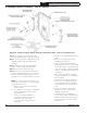
106346-06 - 8/19 3178" SPANNER BAR W/ ADJUSTABLE LEGS 5 34" Figure 1: FORCE OIL Dimensions 1341" FRONT SERVICE CLEARANCE (FLUEWAY CLEANING) TEMP/PRESSURE GAUGE NOTES: 1. THIS DIMENSION INCREASES AND IS CONTROLLED BY SMOKEPIPE ARRANGEMENT. 2. DRAIN VALVE AND RELIEF VALVE/FITTINGS SHIPPED LOOSE. 3. BOILER SHIPPED WITH STANDARD RIGHT HAND HINGE CONFIGURATION, BUT CAN BE CONVERTED TO LEFT HAND HINGE. APPLY CLEARANCE ACCORDINGLY. 19" MIN.
Installation, Operating & Service Manual FORCE 1 General Information (continued) Table 1A: Dimensional Data (See Figure 1) Dimensions See Figure 1 Heat Transfer Surface Area Sq. Ft. Actual Shipping Weight (LB.) “A” “B” “C” Water Content Gallons FORCEOL084E/115-E 17” 24” 5” 7.70 13.29 475 FORCEOL140-E 23” 24” 6” 11.08 20.29 567 FORCEOL182E 29” 30” 6” 14.46 27.29 660 Boiler Model NOTE: 1.
FORCE Installation, Operating & Service Manual 2 Pre-Installation • 30" for flueway cleaning (FORCEOL182-E) b. Clearance from Jacket Left Side Panel - A. INSPECT SHIPMENT carefully for any signs of damage. 1. All equipment is carefully manufactured, inspected and packed. Our responsibility ceases upon delivery of crated boiler to the carrier in good condition. 2. Any claims for damage or shortage in shipment must be filed immediately against the carrier by the consignee.
FORCE Installation, Operating & Service Manual 2 Pre-Installation (continued) 5. For minimum clearances to combustible materials. See Figures 2A and 2B. ! WARNING Adequate combustion and ventilation air must be provided to assure proper combustion and to maintain safe ambient air temperatures. Do not install boiler where gasoline or other flammable vapors or liquids, or sources of hydrocarbons (i.e. bleaches, fabric softeners, etc.) are used or stored.
FORCE Installation, Operating & Service Manual 3 Packaged Boiler Assembly - Trim & Controls A. REMOVE CRATE. 1. Remove all fasteners at crate skid. 2. Lift outside container and remove all other inside protective spacers and bracing. Remove miscellaneous parts carton. B. REMOVE BOILER FROM SKID. 1. To reduce the risk of damage to boiler jacket, use the following procedure to remove from skid, see Figure 3: Step 1.
FORCE Installation, Operating & Service Manual 3 Packaged Boiler Assembly - Trim & Controls (continued) Figure 4A: Partial Front View - Burner Swing Door Mounted to Boiler - Fully Closed and Secured Step 1. Loosen but do not remove left side latching hardware (3/8" x 1-3/4" lg. tap bolt). Step 2. Loosen and remove right side latching hardware (3/8" x 1-3/4" lg. tap bolt and washer). Step 3. Remove left side latching hardware (3/8" x 1-3/4" lg. tap bolt and washer). Step 4. Disconnect power from boiler.
FORCE Installation, Operating & Service Manual 3 Packaged Boiler Assembly - Trim & Controls (continued) Figure 4B: Top View - Burner Swing Door Mounted to Cast Iron Block Assembly (Jacket Removed for Clarity) 106346-06 - 8/19 11
FORCE Installation, Operating & Service Manual 3 Packaged Boiler Assembly - Trim & Controls (continued) 2. Perform routine inspection, service or cleaning as necessary. 3. TO CLOSE BURNER SWING DOOR (see Figures 4A and 4B): Step 1. From the fully open position, rotate Burner Swing Door to the closed position. Step 2. If necessary, place your right hand under the burner air tube to lift upward.
FORCE Installation, Operating & Service Manual 3 Packaged Boiler Assembly - Trim & Controls (continued) 3. Inspect burner swing door insulation for damage and proper type. By design, cast bars on front section between the combustion chamber and between the left and right side 2nd and 3rd pass flueway should make an impression in door insulation to seal the chambers. If insulation is damaged, it must be replaced. 4. Do not close and secure door at this time, proceed to Field Assembly Details, Paragraph F.
FORCE Installation, Operating & Service Manual 3 Packaged Boiler Assembly - Trim & Controls (continued) Figure 6: Limit Sensor Insertion Step 2. Locate (2) 5/8” cable clamps in parts carton. Secure burner wiring harness to front of jacket right side panel with cable clamps and existing jacket screws at top and mid-point. Step 3. Locate the sensor (included in the 36” Remote Mounting Kit).
FORCE Installation, Operating & Service Manual 3 Packaged Boiler Assembly - Trim & Controls (continued) Step 2. Thread 1-1/4" x 1-1/4" x 3/4" NPT tee on opposite end of 5" lg. nipple installed in Step a. NOTE: Based on access for servicing and location of sewer or floor drain, when tightening these fittings, determine if drain valve is to be located on the left or right side.
FORCE Installation, Operating & Service Manual 3 Packaged Boiler Assembly - Trim & Controls (continued) 7. Close the burner swing door and securely seal the door to the boiler front section by reinstalling the hardware and securing the door using procedure previously outlined in Paragraph D of this section. NOTICE: When securing burner swing door make sure door is drawn-in equally on both sides.
FORCE Installation, Operating & Service Manual 4 Water Boiler Piping NOTICE: Failure to pipe boiler as specified in this manual may result in excessive system noise. A. EVALUATE THE EXISTING WATER SYSTEM. Design a piping system and install boiler which will prevent oxygen contamination of boiler water and frequent water additions. 1. There are many possible causes of oxygen contamination such as: a. Addition of excessive make-up water as a result of system leaks. b.
Figure 10A: Recommended Water Piping for Circulator Zoned Heating Systems - Supply Side Circulator FORCE 18 Installation, Operating & Service Manual 4 Water Boiler Piping (continued) 106346-06 - 8/19
Figure 10B: Recommended Water Piping for Zone Valve Zoned Heating Systems - Supply Side Circulator FORCE 106346-06 - 8/19 Installation, Operating & Service Manual 4 Water Boiler Piping (continued) 19
FORCE Installation, Operating & Service Manual 4 Water Boiler Piping (continued) Figure 11: Recommended Piping for Combination Heating and Cooling (Refrigeration) System ! WARNING The use of a low water cut-off device, while not required unless radiation level is below the boiler, is highly recommended. If a low water cut-off is required, it must be mounted in the system piping above the boiler.
FORCE Installation, Operating & Service Manual 5 Indirect Water Heater Piping A. CONNECT INDIRECT DOMESTIC WATER HEATER PIPING as shown in Figures 12A and 12B. Also refer to Figures 10A and 10B. Refer to instructions furnished with Indirect Water Heater for additional information.
FORCE Installation, Operating & Service Manual 6 Natural Draft Venting (Chimney) ! WARNING • Vent this boiler according to these supplemental instructions. Failure to do so may cause products of combustion to enter the home resulting in severe property damage, personal injury or death. • Insufficient Combustion Air Supply may result in the production and release of deadly carbon monoxide (CO) into the home which can cause severe personal injury or death.
FORCE Installation, Operating & Service Manual 6 Natural Draft Venting (Chimney) (continued) FIRECLAY TILE LINED CHIMNEY NOT LESS THAN 8" X 8" X 15' THIMBLE NOTE: ALL HORIZONTAL VENT PIPE SHOULD SLOPE UPWARD NOT LESS THAN ONE INCH IN FOUR FEET. SLOPE UP APPROX.
FORCE Installation, Operating & Service Manual 6 Natural Draft Venting (Chimney) (continued) 5. Draft Regulator – a draft regulator (not supplied with boiler) must be used with this appliance. Refer to Figures 13 and 14. B. CHIMNEY CONNECTOR 1. A chimney connector (vent pipe) is used to connect the boiler to the base of the chimney. The chimney connector should be kept as short as possible. The horizontal length of the chimney connector shall not be greater than 10 feet.
FORCE Installation, Operating & Service Manual 6 Natural Draft Venting (Chimney) (continued) D. STACK TEMPERATURE 1. The temperature of the flue gases has a significant effect on the amount of draft created in a vertical chimney as well as the propensity to create condensate. The higher the stack temperature, the greater the amount of draft that can be generated.
FORCE Installation, Operating & Service Manual 7 Direct Venting / Air Intake Piping A. GENERAL GUIDELINES 1. Direct Vent system must be installed in accordance with these instructions and applicable provisions of local building codes. Contact your local fire and building officials on specific requirements for restrictions and the installation of fuel oil burning equipment.
FORCE Installation, Operating & Service Manual 7 Direct Venting / Air Intake Piping (continued) d. Not less than 7 ft above grade when located above public walkway. e. Not less than 3 ft (as measured to side of vent termination) from an inside corner of an L-shaped structure. f. Not less than 1 ft from the nearest surface of the terminal to a roof soffit. g. Not directly above, or, not less than 6 ft horizontally from an oil tank vent or gas meter. h.
FORCE Installation, Operating & Service Manual 7 Direct Venting / Air Intake Piping (continued) D. INSTALLING THE FLEX OIL VENT PIPE FROM THE VENT TERMINATION TO THE BOILER FLUE OUTLET 1.
FORCE Installation, Operating & Service Manual 7 Direct Venting / Air Intake Piping (continued) Table 6: Flex Vent / Vent Termination Pipe Diameters Boiler Model FORCEOL140-E FORCEOL182-E Boiler Flue Outlet Collar OD (Inch) Vent Hood Inner Pipe Diameter (Inch) 6 Flex Oil Vent Pipe Inner Pipe Diameter (Inch) * Flue Outlet Collar to Vent Pipe Adapter (Inch) 5 6 to 5 NOTE: * The model specific Direct Vent (FDVS) Kit Cartons contain adapters (reducers) (see Table 6) to connect boiler flue outlet colla
FORCE Installation, Operating & Service Manual 7 Direct Venting / Air Intake Piping (continued) 7. Apply sealant; firstly, between the stop bead and retainer bead at the end of the vent termination inner pipe; secondly, between the stop bead and retainer bead at the end of the appliance adapter. See Figure 23. 8. Assemble supplied inner pipe clamp halves with 1/4-20 bolts and square nuts; position the inner pipe clamps ¼” from the end of inner vent pipe, on vent pipe opposite ends. 9.
FORCE Installation, Operating & Service Manual 7 Direct Venting / Air Intake Piping (continued) ! WARNING DO NOT reduce size of air intake pipe. Figure 24: Vent Pipe Assembly to Vent Termination Inner Pipe & Appliance Adapter G. INSTALLING THE AIR INTAKE PIPING FROM DIRECT VENT TERMINATION TO BURNER OUTSIDE AIR ADAPTER 1.
FORCE Installation, Operating & Service Manual 7 Direct Venting / Air Intake Piping (continued) 12. Assemble the vacuum relief valve balance weight onto the gate. Refer to the vacuum relief valve manufacturer’s instructions for details. 13. Mount the assembled vacuum relief valve gate with balance weight into the tee and fasten with a screw and nut in collar tabs. To insure proper operation, the gate must be level across the pivot point and plumb.
FORCE Installation, Operating & Service Manual 8 Electrical ! DANGER Positively assure all electrical connections are unpowered before attempting installation or service of electrical components or connections of the boiler or building. Lock out all electrical boxes with padlock once power is turned off. ! WARNING • Failure to properly wire electrical connections to the boiler may result in serious physical harm. • Electrical power may be from more than one source.
Figure 27: Schematic Wiring Diagram HydroStat 3250 Control with Beckett AFG Series Burners FORCE 34 Installation, Operating & Service Manual 8 Electrical (continued) 106346-06 - 8/19
FORCE Installation, Operating & Service Manual Figure 28: Schematic Wiring Diagram HydroStat Control to Beckett NX Burners 8 Electrical (continued) 106346-06 - 8/19 35
FORCE Installation, Operating & Service Manual 8 Electrical (continued) NOTE: APPLY THIS BURNER SCHEMATIC TO APPROPRIATE STEAM OR WATER BOILER CONTROL SCHEMATIC, REFER TO Figure 27 NOTE: APPLY THIS BURNER SCHEMATIC TO APPROPRIATE STEAM OR WATER BOILER CONTROL SCHEMATIC, REFER TO Figure 28 Figure 29: Schematic Wiring Diagrams 36 106346-06 - 8/19
FORCE Installation, Operating & Service Manual 9 Oil Piping ! WARNING A. GENERAL 1. Use flexible oil line(s) so the burner swing door can be opened without disconnecting the oil supply piping. 2. A supply line fuel oil filter is recommended as a minimum for all firing rates but a pleated paper fuel oil filter is recommended for the firing rates below 1.0 GPH to prevent nozzle fouling. 3. Use Flared fittings only. Cast iron fittings cannot be used. NOTICE: Do not use compression fittings.
FORCE Installation, Operating & Service Manual 9 Oil Piping (continued) C. TWO PIPE OIL LINES 1. For two piped systems, where more lift is required, the two-stage fuel unit is recommended. Table 7 (two-stage) and Table 8 (single-stage) show allowable lift and lengths of 3/8 inch and 1/2 inch OD tubing for both suction and return lines. Refer to Figure 31. 2. Follow the oil pump manufacturer’s recommendations on the proper connections for a two pipe system.
FORCE Installation, Operating & Service Manual 10 System Start-Up ! WARNING All boilers equipped with burner swing doors have a potential hazard which can cause severe property damage, personal injury or loss of life if ignored. Before opening swing door, turn off service switch to boiler to prevent accidental firing of burner outside the combustion chamber. Be sure to tighten swing door fastener completely when service is completed.
FORCE Installation, Operating & Service Manual 10 System Start-Up (continued) D. ADJUST CONTROL SETTINGS with burner service switch turned “ON”. 1. SET ROOM THERMOSTAT about 10°F below room temperature. 2. PRESS RED RESET BUTTON on burner primary control, hold for ten (10) seconds and release to reset the control. 3. CHECKOUT Put the system into operation and observe at least one complete cycle to make sure that the controller operates properly.
FORCE Installation, Operating & Service Manual Figure 32: "L1" and "V1" Head Electrode Positioning and Gun Setting (Beckett AFG) 10 System Start-Up (continued) 106346-06 - 8/19 41
FORCE 10 System Start-Up (continued) m. Loosening the splined nut and lower acorn nut, and, turning the adjustment screw, either forward or, rearwards, will adjust the head/air plate. DO NOT LOOSEN UPPER LEFT ACORN NUT, which locks zero head/ air setting. See Figure 35. n. OPEN ALL SHUT-OFF VALVES in the oil supply line to the burner. o. ATTACH A PLASTIC HOSE TO FUEL PUMP VENT/BLEED FITTING and place the other hose end into an empty container to catch the oil. p.
FORCE Installation, Operating & Service Manual 10 System Start-Up (continued) c. To check the cut-off pressure, deadhead a reliable pressure gauge onto the copper connector tube attached to the nozzle port. Run the burner for a short period of time. Shut the burner off. The pressure should drop and hold. d. Turn "OFF" the burner. Remove the pressure gauge and install port/bleeder plug and/or reconnect the nozzle port line and tighten. Start the burner again. G. ADJUST OIL BURNER WHILE OPERATING.
FORCE Installation, Operating & Service Manual 10 System Start-Up (continued) Figure 37: Cad Cell Location clean, then replace and readjust oil pressure. If dripping or after burn persist replace fuel pump. I. TEST CONTROLS. 1. Check thermostat operation. Raise and lower thermostat setting as required to start and stop burner. ! WARNING Before installation of the boiler is considered complete, the operation of all boiler controls must be checked, particularly the primary control and high limit control.
FORCE Installation, Operating & Service Manual 10 System Start-Up (continued) NOTE: DO NOT remove "T-T" jumper unless wiring diagram indicates a direct connection from thermostat and/or tankless heater HydroStat 3250 control to the oil burner primary control's "T-T" terminal. Refer to appropriate wiring diagram, see Figures 27 and 28. vi.
FORCE Installation, Operating & Service Manual 10 System Start-Up (continued) c. Allow the temperature to drop below control setting. The burner must restart. d. Boiler installation is not considered complete until this check has been made. 5. CHECK LOW WATER CUT-OFF a. Press and hold the test / settings button for 5 seconds. b. The red low water light should illuminate and the burner circuit (B1 & B2) should deenergize. 6.
FORCE Installation, Operating & Service Manual 11 Operating Refer to the HydroStat 3250 Installation Instructions and Operating Manual included with these instructions. IMPORTANT This boiler is equipped with a feature that saves energy by reducing the boiler water temperature as the heating load decreases. This feature is equipped with an override which is provided primarily to permit the use of an external energy management system that serves the same function.
FORCE Installation, Operating & Service Manual 12 Service and Maintenance Instructions A. WATER BOILERS: 1. Filling of boiler and system. GENERAL — In a hot water heating system, the boiler and entire system (other than the expansion tank) must be full of water for satisfactory operation. Water should be added to the system until the boiler pressure gauge registers 12 psi. To insure that the system is full, water should come out of all air vents when opened. 2. BOILING OUT OF BOILER AND SYSTEM.
FORCE Installation, Operating & Service Manual 12 Service and Maintenance Instructions (continued) IMPORTANT IF, DURING NORMAL OPERATION, IT IS NECESSARY TO ADD MORE WATER THAN INDICATED BELOW, CONSULT A QUALIFIED SERVICE TECHNICIAN TO CHECK YOUR SYSTEM FOR LEAKS. Gallons Per Gallons Per Boiler Model Month Year FORCEOL084-E 0.20 2 FORCEOL115-E 0.20 2 FORCEOL140-E 0.25 3 FORCEOL182-E 0.30 4 C.
FORCE Installation, Operating & Service Manual 13 Boiler Cleaning ! WARNING This boiler contains controls which may cause the boiler to shut down and not restart without service. If damage due to frozen pipes is a possibility, the heating system should not be left unattended in cold weather; or appropriate safeguards and alarms should be installed on the heating system to prevent damage if the boiler is inoperative. A. CLEAN THE FLUEWAYS (See Figure 39). 1.
FORCE Installation, Operating & Service Manual 13 Boiler Cleaning (continued) Figure 39: Cleaning of Boiler Flueways ! WARNING The boiler must be connected to an approved chimney in good condition. Serious property damage could result if the boiler is connected to a dirty or inadequate chimney. The interior of the chimney flue must be inspected and cleaned before the start of the heating season and should be inspected periodically throughout the heating season for any obstructions.
FORCE Installation, Operating & Service Manual 13 Boiler Cleaning (continued) Important Product Safety Information: Refractory Ceramic Fiber Product WARNING Some boiler components use materials that contain refractory ceramic fibers (RCF). RCF has been classified as a possible human carcinogen. When exposed to elevated temperatures, RCF may change into crystalline silica, a known carcinogen.
FORCE Installation, Operating & Service Manual 14 Troubleshooting A. COMBUSTION 1. NOZZLES — Although the nozzle is a relatively inexpensive device, its function is critical to the successful operation of the oil burner. The selection of the nozzle supplied with the FORCE OIL boiler is the result of extensive testing to obtain the best flame shape and efficient combustion. Other brands of the same spray angle and spray pattern may be used but may not perform at the expected level of CO2 and smoke.
FORCE Installation, Operating & Service Manual 14 Troubleshooting (continued) NOTICE: CHECK TEST PROCEDURE. A very good test for isolating fuel side problems is to disconnect the fuel system and with a 24" length of tubing, fire out of an auxiliary five gallon pail of clean, fresh, warm #2 oil from another source. If the burner runs successfully when drawing out of the auxiliary pail then the problem is isolated to the fuel or fuel lines being used on the jobsite. B. OIL PRIMARY CONTROL (Oil Primary) 1.
FORCE Installation, Operating & Service Manual 15 Service Parts All FORCE™ Repair Parts may be obtained by contacting your local Ferguson branch.
FORCE Installation, Operating & Service Manual Bare Boiler Assembly 15 Service Parts (continued) 56 106346-06 - 8/19
FORCE Installation, Operating & Service Manual 15 Service Parts (continued) FORCE OIL Bare Boiler Assembly Item No.
FORCE Jacket Assembly 15 Service Parts (continued) Installation, Operating & Service Manual 58 106346-06 - 8/19
FORCE Installation, Operating & Service Manual 15 Service Parts (continued) Item No 2A Description Complete Jacket Carton Includes: Labels and Hardware Part Number FORCEOL84E FORCEOL115E 106443-02 1 1 106443-03 1 106443-04 1 109553-02 2B Wrap Around Insulation 1 FORCEOL140E FORCEOL182E 1 1 1 109553-03 1 109553-04 1 2C Temperature & Pressure Gauge 105894-01 1 1 1 1 2D HydroStat 3250 Plus Includes: Remote Mounting Kit & 36” Sensor 109685-01 1 1 1 1 2E Electro-Well, 1/2”
FORCE Installation, Operating & Service Manual 15 Service Parts (continued) Item No. Description Part No. FORCEOL140-E FORCEOL182-E 106401-01 1 1 Adapter, Appliance, FDVS, 5-6 1 1 Clamp, 6" Appliance, FDVS-6, Half 2 2 2 2 Assy., Cover Ring, FDVS-5 2 2 Clamp, Inner Pipe FDVS-5, Half 4 4 1 1 3. DIRECT VENT KITS AND PARTS Direct Vent Conversion Kit Not Shown Assy., Cover Sleeve, FDVS-5 Included in kit 4. FLEX OIL VENT PIPE FOR DIRECT VENT Not Shown 5" Dia. x 10 ft.
FORCE Installation, Operating & Service Manual Beckett AFG Burner 15 Service Parts (continued) 106346-06 - 8/19 61
FORCE 15 Service Parts (continued) Installation, Operating & Service Manual BECKETT AFG OIL BURNER PART NOS. FOR FORCE OIL SERIES BOILERS NATURAL DRAFT APPLICATIONS NOTE: When ordering parts always give the serial and model numbers shown on the boiler and burner. Also provide the name of the part(s) and part number as listed below. Boiler Model FORCEOL84-E Air Tube Combination AFG70MQASN AFG70MPASN AFG70MMAQN AFG70MLASN Beckett's Spec. No.
FORCE Installation, Operating & Service Manual Beckett NX Burner 15 Service Parts (continued) 106346-06 - 8/19 63
FORCE Installation, Operating & Service Manual 15 Service Parts (continued) BECKETT NX OIL BURNER PART NOS. FOR FORCE OIL SERIES BOILERS DIRECT VENT APPLICATIONS NOTE: When ordering parts always give the serial and model numbers shown on the boiler and burner. Also provide the name of the part(s) and part number as listed below. Item No.
FORCE Installation, Operating & Service Manual 16 Burner Specifications Boiler Model Burner Input (GPH) Burner Model FORCEOL084-E 0.60 AFG FORCEOL115-E 0.80 AFG FORCEOL140-E 1.00 AFG FORCEOL182-E 1.30 AFG Nozzle Air Pump Head Insertion Approx. Baffle Air Band Shutter Pressure Type Depth Shipped Location (setting) (setting) (PSI) (setting) (Inch) CO2 (%) (pass) 0.50 x 45W Delavan 0.65 x 45B Delavan 0.85 x 60B Delavan Approx. Stack Temp.
FORCE Installation, Operating & Service Manual Appendix A: Aftermarket Low Water Cut Off (LWCO) On Hot Water Boilers ! WARNING • DO NOT ATTEMPT to cut factory wires to install an aftermarket Low Water Cut Off (LWCO). Only use connections specifically identified for Low Water Cut Off. • In all cases, follow the Low Water Cut Off (LWCO) manufacturer's instructions.
FORCE Installation, Operating & Service Manual Appendix A: Aftermarket Low Water Cut Off (LWCO) On Hot Water Boilers (continued) A 24 VAC LWCO is used primarily for gas fired boilers where a 24 volt control circuit exists within the boiler. However, a 24 VAC LWCO can only be used if the boiler manufacturer has provided piping and wiring connections and instructions to allow for this application. 106346-06 - 8/19 How to Test Shut off fuel supply. Lower water level until water level is BELOW the LWCO.
FORCE Installation, Operating & Service Manual SERVICE RECORD DATE SERVICE PERFORMED __________________________________________________________________________________________________ __________________________________________________________________________________________________ __________________________________________________________________________________________________ __________________________________________________________________________________________________ ___________________________