
ProSelect Force Hot Water Oil Boiler Installation Manual

14
106346-06 - 8/19
FORCE
Installation, Operating & Service Manual
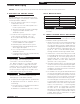
Step 2. Locate (2) 5/8” cable clamps in
parts carton. Secure burner wiring
harness to front of jacket right side
panel with cable clamps and existing
jacket screws at top and mid-point.
Step 3. Locate the sensor (included in the
36” Remote Mounting Kit). Carefully
connect sensor into the HydroStat
3250 Plus circuit board by pressing
connector on sensor unit into mating
connector on circuit board. Fish the
sensor through top knockout; allow
adequate slack in sensor cable. Insert
sensor into Electro-well located in the
front section until it rests against the
bottom of the well. Secure sensor to
Electro-well with supplied well cap
(included in the 36” Remote Mounting
Kit).
Step 4. Locate (2) 3/16” cable clamps in
parts carton. Secure sensor wire to top
jacket panel and side jacket panel with
cable clamps with self-tapping sheet-
metal screws (included) as shown in
Figure 5.
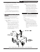
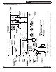
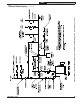
3. Install return injector piping and relief valve, refer
to Figure 7.
Locate the return pipe fittings and injector. Apply
sealant to the 2” NPT injector threads. Insert
injector into 2” NPT upper rear tapping on rear
section. Thread 2” NPT x 1-1/2” Reducing Elbow
onto 2” NPT injector.
NOTE: Based on system return piping and
access to service boiler, see Figures 1,
10A and 10B, predetermine if injector
piping orientation is to be positioned for
vertical, horizontal left or horizontal right
side return piping as shown in Figure 7.
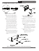
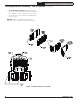
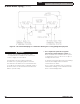
4. Install drain valve, see Figure 8.
Step 1. Apply pipe sealant to both ends
of 1-1/4" NPT x 5" lg. nipple. Thread
nipple into 1-1/4" NPT lower rear
tapping on rear section.
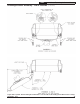
Figure 7: Return Injector Piping and
Relief Valve Assembly Details
Figure 8: Piping Arrangement for Drain Valve and Indirect Water Heating Return
Figure 6: Limit Sensor Insertion
3 Packaged Boiler Assembly - Trim & Controls (continued)