
ProSelect Force Hot Water Oil Boiler Installation Manual

43
106346-06 - 8/19
FORCE
Installation, Operating & Service Manual
c. To check the cut-off pressure, deadhead
a reliable pressure gauge onto the copper
connector tube attached to the nozzle port.
Run the burner for a short period of time.
Shut the burner off. The pressure should
drop and hold.
d. Turn "OFF" the burner. Remove the pressure
gauge and install port/bleeder plug and/or
reconnect the nozzle port line and tighten.
Start the burner again.
G. ADJUST OIL BURNER WHILE
OPERATING. (flame present)
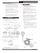
1. ADJUST DRAFT REGULATOR for a draft
of zero inches (water gauge) in the canopy
(see Figure 15) after chimney has reached
operating temperature and while burner is
running (at least five minutes).
See Table 9 at the end of this manual for
additional details.
2. READJUST THE AIR DAMPER SETTING (Air
Band/Air Shutter) on burner for a light orange
colored flame while the draft in the canopy is
zero inches water column ("w.c.). Use a smoke
tester and adjust air for minimum smoke (not
to exceed #1) with a minimum of excess air.
Make final check using suitable instrumentation
to obtain a CO
2
of 11.5 to 13.0% with draft
of zero inches water column ("w.c.) (water
gauge) in canopy. These settings will assure
a safe and efficient operating condition. If the
flame appears stringy instead of a solid fire, try
another nozzle of the same type. Flame should
be solid and compact. After all adjustments
are made recheck for a draft of zero inches
water column ("w.c.) in the canopy. Replace
plug at completion.
See Table 9 (at the end of this manual) for
details regarding the overfire pressure when
baffles are both installed and removed.
NOTE: Paragraph G, Step 1 MUST BE
repeated every time the Air Damper Setting is
readjusted.
3. ONLY READJUST THE HEAD SETTING, if
necessary.
Beckett AFG Burners
a. FORCEOL084-E through FORCEOL140-E
Beckett MB(L1 & L2) Head burners have a
fixed head which are non-adjustable.
b. FORCEOL182-E:
Beckett MD(V1) (variable) Head burners
have the ability to control air by moving the
head. It might be necessary to move the
head forward or back one position at a time
to optimize the smoke and CO
2
readings.
See Figure 32.
Beckett NX Burners
Move the Head/Air Setting forward or back one
position at a time to optimize the smoke and
CO
2
readings. See Figure 35.
NOTE: Step outlined in Paragraph G, Steps
1 and 2 above MUST BE repeated every
time the Head or Air Damper Setting is
readjusted.
WARNING
DO NOT loosen or remove any oil line fittings
while burner is operating.
4. FLAME FAILURE
The FORCE OIL boiler controls operate the
burner automatically. If for unknown reasons
the burner ceases to fire and the reset button
on the primary control has tripped, the burner
has experienced ignition failure. Refer to Oil
Primary Control features, Paragraph I, Step 2 of
this section and Section XIV, Troubleshooting,
Paragraph B. If the failure re-occurs, call your
heating contractor immediately before pressing
the reset button.
WARNING
DO NOT attempt to start the burner when
excess oil has accumulated, when the boiler is
full of vapor, or when the combustion chamber
is very hot.
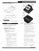
5. CAD CELL LOCATION AND SERVICE
The burner is supplied with a cadmium
sulfide flame detector mounted at the factory,
mounted on the bottom of the electronic
ignitor. See Figure 37. To service cad cell or
to replace the plug in portion, swing open the
ignitor. After service is complete, be sure to
fasten down the ignitor.
H. CHECK FOR CLEAN CUT OFF OF
BURNER.
1. AIR IN THE OIL LINE between fuel unit
and nozzle will compress when burner is on
and will expand when burner stops, causing
oil to squirt from nozzle at low pressure as
burner slows down and causing nozzle to drip
after burner stops. Usually cycling the burner
operation about 5 to 10 times will rid oil line of
this air.
2. IF NOZZLE CONTINUES TO DRIP, repeat
Paragraph H, Step 1 above. If this does not
stop the dripping, remove cut-off valve and
seat, and wipe both with a clean cloth until
10 System Start-Up (continued)
!
!