ILX34-AENWG POINT I/O Platform Wireless Point I/O Adapter July 31, 2009 SETUP GUIDE
Important User Information Important: Power must be provided from a limited power source. Because of the variety of uses for the products described in this publication, those responsible for the application and use of these products must satisfy themselves that all necessary steps have been taken to assure that each application and use meets all performance and safety requirements, including any applicable laws, regulations, codes and standards.
Do not touch circuit components inside the equipment. If available, use a static-safe workstation. When not in use, store the equipment in appropriate static-safe packaging. Caution: POINT I/O is grounded through the DIN-rail to chassis ground. Use zinc-plated, yellow-chromated steel DIN-rail to assure proper grounding.
European Hazardous Location Approval European Zone 2 Certification (The following applies when the product bears the EEx Marking) This equipment is intended for use in potentially explosive atmospheres as defined by European Union Directive 94/9/EC.
La substitution de composants peut rendre cet équipement inadapté à une utilisation en environnement de Classe 1, Division 2. S'assurer que l'environnement est classé non dangereux avant de changer les piles. Your Feedback Please We always want you to feel that you made the right decision to use our products. If you have suggestions, comments, compliments or complaints about the product, documentation, or support, please write or call us. ProSoft Technology 5201 Truxtun Ave.
Contents Setup Guide ILX34-AENWG ♦ POINT I/O Platform Wireless Point I/O Adapter Contents Important User Information ................................................................................................................. 2 Important Installation Instructions: Radio Modules ............................................................................. 3 Agency Approval & Certification .........................................................................................................
ILX34-AENWG ♦ POINT I/O Platform Wireless Point I/O Adapter Page 8 of 79 Contents Setup Guide ProSoft Technology, Inc.
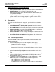
Scope Setup Guide 1 ILX34-AENWG ♦ POINT I/O Platform Wireless Point I/O Adapter Scope In This Chapter Learning Objectives................................................................................. 9 ProSoft Technology Documentation........................................................ 9 Prerequisites .........................................................................................
ILX34-AENWG ♦ POINT I/O Platform Wireless Point I/O Adapter Scope Setup Guide Additional documentation, tools, and product support 1.3 Email Technical Support: Send your support questions to Support@prosofttechnology.com Web Site Support: Visit the ProSoft Technology web site at www.prosoft-technology.com to download additional documentation, tools and application information Telephone Support: Please call ProSoft Technology Technical Support at: (Country Code 1+) 661-716-5100.
Scope Setup Guide ILX34-AENWG ♦ POINT I/O Platform Wireless Point I/O Adapter Pentium® II 450 MHz minimum.
ILX34-AENWG ♦ POINT I/O Platform Wireless Point I/O Adapter Page 12 of 79 Scope Setup Guide ProSoft Technology, Inc.
About the Example Applications Setup Guide 2 ILX34-AENWG ♦ POINT I/O Platform Wireless Point I/O Adapter About the Example Applications In This Chapter System Components ............................................................................. 14 Set Up the Hardware .............................................................................
ILX34-AENWG ♦ POINT I/O Platform Wireless Point I/O Adapter 2.1 About the Example Applications Setup Guide System Components We used the following components for the example applications. You need the same or similar components to set up your own control system using POINT I/O modules on an EtherNet/IP network.
Procedures Setup Guide 3 ILX34-AENWG ♦ POINT I/O Platform Wireless Point I/O Adapter Procedures In This Chapter 3.1 Install the Configuration Tools ............................................................... 15 Physical Setup....................................................................................... 16 Verify Communication ........................................................................... 55 Install the Configuration Tools 3.1.
ILX34-AENWG ♦ POINT I/O Platform Wireless Point I/O Adapter 3.2 Procedures Setup Guide Physical Setup 3.2.1 Adapter Components The Wireless Point I/O Adapter is a communications adapter for POINT I/O modules. The adapter provides an interface for controlling and communicating with POINT I/O modules from an Ethernet network. Page 16 of 79 ProSoft Technology, Inc.
Procedures Setup Guide ILX34-AENWG ♦ POINT I/O Platform Wireless Point I/O Adapter 3.2.2 Install the Wireless Point I/O Adapter on the DIN-rail Warning: You must follow all safety instructions when installing this or any other electronic devices. Failure to follow safety procedures could result in damage to hardware or data, or even serious injury or death to personnel.
ILX34-AENWG ♦ POINT I/O Platform Wireless Point I/O Adapter Procedures Setup Guide 3.2.3 Configure the Wireless Access Point Although the ILX34-AENWG can communicate with any 802.11b/g Access Point radio, ProSoft Technology recommends the RadioLinx series Industrial Broadband radios wherever performance and compatibility are required. The following configuration steps are for the RLXIB-IHW. Use the examples in these steps to configure your own Access Point to work with the ILX34-AENWG.
Procedures Setup Guide ILX34-AENWG ♦ POINT I/O Platform Wireless Point I/O Adapter IP Address: The IP address for all radios must be within the same subnet, and each radio requires its own unique IP address. You can assign static IP addresses, as in this example, or you can use DHCP (Dynamic Host Control Protocol) to manage and assign IP addresses automatically.
ILX34-AENWG ♦ POINT I/O Platform Wireless Point I/O Adapter Procedures Setup Guide 3.2.4 Configure the IP Address with the Thumbwheel Switches Before you can connect to the ILX34-AENWG for the first time, you must configure its IP address. The simplest way to set the IP address for your initial connection is to use the thumbwheel switches on the front of the adapter. The three thumbwheel switches represent the final octet for the private IP address 192.168.1.
Procedures Setup Guide ILX34-AENWG ♦ POINT I/O Platform Wireless Point I/O Adapter 3.2.5 Connect Power to the Adapter The ILX34-AENWG adapter requires an external source of DC voltage. The DC source voltage should be 24V nominal, with a range of 10V to 28.8V. Refer to the following illustrations for wiring information. Caution: Do not connect 120/240V ac power to this supply. Warning: If you connect or disconnect wiring while the field-side power is on, an electrical arc can occur.
ILX34-AENWG ♦ POINT I/O Platform Wireless Point I/O Adapter Procedures Setup Guide When you power up the POINT I/O for the first time, the adapter must assign addresses to every module in the backplane. POINT I/O modules are all initially configured at the same address. When you first apply power, all but one module on the backplane should show a solid red Module Status LED. One by one, the adapter resets these modules and assigns addresses.
Procedures Setup Guide ILX34-AENWG ♦ POINT I/O Platform Wireless Point I/O Adapter 3.2.7 Configure the ILX34-AENWG for Wireless Access You can configure the ILX34-AENWG's wireless settings from the MODULE PROPERTIES dialog box in RSLogix 5000, or from the ILX34-AENWG's web page. The first time you configure the adaptor, you should use the adapter's web page.
ILX34-AENWG ♦ POINT I/O Platform Wireless Point I/O Adapter Procedures Setup Guide The adapter's home page consists of a tree view in the left pane for navigation, and an information pane in the middle. The right column contains links for additional resources and information. To view the contents of a folder, click the EXPAND button. To select a page to view, click the page title in the tree view.
Procedures Setup Guide ILX34-AENWG ♦ POINT I/O Platform Wireless Point I/O Adapter The WIRELESS SETTINGS page opens when you select the CONFIGURATION folder in the menu on the left side of the page, and then click the WIRELESS SETTINGS link. Use this page to configure the radio settings for the adapter. Important: The values on this page are in non-volatile memory. Changes to these parameters do not take effect until you reset or cycle power to the ILX34-AENWG adapter.
ILX34-AENWG ♦ POINT I/O Platform Wireless Point I/O Adapter Procedures Setup Guide Field Description WPA Passphrase To use WPA2/AES encryption on packets sent between the radios, enter a WPA2/AES pass phrase of between eight and 63 normal keyboard characters. This phrase automatically generates an encryption key of 128 hexadecimal characters. This field is only available if you select WPA2/AES as the encryption type.
Procedures Setup Guide ILX34-AENWG ♦ POINT I/O Platform Wireless Point I/O Adapter 3.2.8 Configure the Application Create a New RSLogix 5000 Project Note: The following steps require RSLogix 5000 version 17 or newer, and a processor with firmware compatible with this version of RSLogix 5000. To use the ILX34-AENWG adapter with an earlier version of RSLogix 5000 or the processor firmware, please refer to Using the ILX34AENWG with Earlier Versions of RSLogix 5000.
ILX34-AENWG ♦ POINT I/O Platform Wireless Point I/O Adapter Procedures Setup Guide Create the Network 1 Right-click I/O CONFIGURATION and choose NEW MODULE… 2 Expand the COMMUNICATIONS node, and then select the ETHERNET BRIDGE module that matches your hardware. This example uses a 1756-ENBT/A module. Note: If you are prompted to "Select Major Revision", choose the lower of the available revision numbers. Page 28 of 79 ProSoft Technology, Inc.
Procedures Setup Guide ILX34-AENWG ♦ POINT I/O Platform Wireless Point I/O Adapter 3 Name the ENBT/A module, then set the IP Address and slot location in the local rack with the ControlLogix processor. 4 Click OK. Create the Adapter 1 Next, select the 1756-ENBT module that you just created in the Controller Organization pane and click the right mouse button to open a shortcut menu. On the shortcut menu, choose NEW MODULE. ProSoft Technology, Inc.
ILX34-AENWG ♦ POINT I/O Platform Wireless Point I/O Adapter Procedures Setup Guide 2 In the SELECT MODULE dialog box, click the VENDOR tab, and then expand the PROSOFT TECHNOLOGY node. Click the BY VENDOR tab, expand the PROSOFT TECHNOLOGY node, and then select ILX34-AENWG. 3 Name the ILX34-AENWG adapter, and set the IP address. Important: The IP address on the ILX34-AENWG's thumbwheel switches must match the IP address you enter here. Page 30 of 79 ProSoft Technology, Inc.
Procedures Setup Guide ILX34-AENWG ♦ POINT I/O Platform Wireless Point I/O Adapter Configure Chassis Size The ILX34-AENWG requires configuration of its chassis size before you can make any I/O connections. The default setting for the chassis size is 1 slot, which represents the adapter by itself, and allows for no I/O. You must set the chassis size to a number equaling 1 slot for the adapter plus 1 slot for each I/O module present in the adapter's backplane.
ILX34-AENWG ♦ POINT I/O Platform Wireless Point I/O Adapter Procedures Setup Guide 3.2.9 Example 1 - Direct Connection and Rack Optimization This example configures your ILX34-AENWG for both direct connection and rack optimization using RSLogix 5000 software. You can mix communication formats for different I/O modules communicating through the same adapter. I/O modules set up to use rack optimization communicate at the rate of the RPI configured for the ILX34-AENWG adapter.
Procedures Setup Guide 3 ILX34-AENWG ♦ POINT I/O Platform Wireless Point I/O Adapter In the MODULE PROPERTIES dialog, enter the following information: a) Name b) Slot In the Module Definition area, click the CHANGE ... button, and change the Connection type from Rack Optimization (default) to DATA. ProSoft Technology, Inc.
ILX34-AENWG ♦ POINT I/O Platform Wireless Point I/O Adapter 4 Procedures Setup Guide Click the CONNECTION tab, and then change the RPI value for the module from 20 (the default) to 50 (the recommended value for analog or specialty modules). This value determines how often to exchange data with the ILX34AENWG adapter. Important: To avoid overloading the ILX34-AENWG adapter, we recommend that RPI be no less than 10 ms for rack connections and 50 ms for direct connections.
Procedures Setup Guide ILX34-AENWG ♦ POINT I/O Platform Wireless Point I/O Adapter Add the Digital Output Module and Configure for Rack Optimization 1 Right-click the ILX34-AENWG adapter under the I/O Configuration folder and select NEW MODULE. 2 In the SELECT MODULE dialog box, choose the 1734-OV4E digital output module from the list, and click OK. ProSoft Technology, Inc.
ILX34-AENWG ♦ POINT I/O Platform Wireless Point I/O Adapter 3 Procedures Setup Guide In the MODULE PROPERTIES dialog, enter the following information: a) Name b) Slot In the MODULE DEFINITION area of the dialog box, notice that the default Connection type is RACK OPTIMIZATION. 4 Click the CONNECTION tab, and then change the RPI value for the module from 20 (the default) to 10 (the recommended value for digital modules). This value determines how often to exchange data with the ILX34-AENWG adapter.
Procedures Setup Guide 5 ILX34-AENWG ♦ POINT I/O Platform Wireless Point I/O Adapter Click OK save the configuration. The following illustration shows the I/O Configuration for this project. Download the Sample Program to the Processor Note: The key switch on the front of the ControlLogix processor must be in the REM or PROG position. 1 2 3 4 If you are not already online with the processor, open the COMMUNICATIONS menu, and then choose DOWNLOAD. RSLogix will establish communication with the processor.
ILX34-AENWG ♦ POINT I/O Platform Wireless Point I/O Adapter Procedures Setup Guide Verify the Chassis Size You must configure the chassis size for the ILX34-AENWG before you can make any I/O connections (page 31). The default setting for the chassis size is 1 slot, which represents the adapter by itself.
Procedures Setup Guide ILX34-AENWG ♦ POINT I/O Platform Wireless Point I/O Adapter 4 Click the CHASSIS SIZE tab, and then click the CLICK SET CHASSIS SIZE IN MODULE button. 5 This action opens a notification dialog box. Take any necessary steps to prevent hazardous conditions, and then click OK to dismiss the dialog box. ProSoft Technology, Inc.
ILX34-AENWG ♦ POINT I/O Platform Wireless Point I/O Adapter Procedures Setup Guide 6 Notice the chassis size in the module has been updated to match the hardware configuration. 7 Click OK to dismiss the Module Properties dialog box. At this point, your POINTBus status LED should be solid green. All the yellow triangles in your I/O configuration should be gone. 8 Open the FILE menu, and then click SAVE to save the project. Page 40 of 79 ProSoft Technology, Inc.
Procedures Setup Guide ILX34-AENWG ♦ POINT I/O Platform Wireless Point I/O Adapter View Module Data You can view module data and communication status in the controller tags in RSLogix 5000. The following illustration shows the ILX34-AENWG configured with the sample application.
ILX34-AENWG ♦ POINT I/O Platform Wireless Point I/O Adapter Procedures Setup Guide 3.2.10 Example 2 - Direct Connection In this example, a ControlLogix controller communicates with POINT I/O modules via the ILX34-AENWG adapter using a direct connection. The adapter makes a direct connection to each of the modules referenced by the data. Attention: You must use series C POINT I/O modules with the ILX34-AENWG adapter. Series A or B POINT I/O modules will not work with this adapter.
Procedures Setup Guide 3 ILX34-AENWG ♦ POINT I/O Platform Wireless Point I/O Adapter In the MODULE PROPERTIES dialog, enter the following information: a) Name b) Slot In the Module Definition area, click the CHANGE ... button, and change the Connection type from Rack Optimization (default) to DATA. ProSoft Technology, Inc.
ILX34-AENWG ♦ POINT I/O Platform Wireless Point I/O Adapter 4 Procedures Setup Guide Click the CONNECTION tab, and then change the RPI value for the module from 20 (the default) to 50 (the recommended value for analog or specialty modules). This value determines how often to exchange data with the ILX34AENWG adapter. Important: To avoid overloading the ILX34-AENWG adapter, we recommend that RPI be no less than 10 ms for rack connections and 50 ms for direct connections.
Procedures Setup Guide ILX34-AENWG ♦ POINT I/O Platform Wireless Point I/O Adapter Add the Digital Output Module and Configure for Direct Connection 1 Right-click the ILX34-AENWG adapter under the I/O Configuration folder and select NEW MODULE. 2 In the SELECT MODULE dialog box, choose the 1734-OV4E digital output module from the list, and click OK. ProSoft Technology, Inc.
ILX34-AENWG ♦ POINT I/O Platform Wireless Point I/O Adapter 3 Procedures Setup Guide In the MODULE PROPERTIES dialog, enter the following information: a) Name b) Slot In the Module Definition area, click the CHANGE ... button, and change the Connection type from Rack Optimization (default) to DATA. Page 46 of 79 ProSoft Technology, Inc.
Procedures Setup Guide ILX34-AENWG ♦ POINT I/O Platform Wireless Point I/O Adapter 4 Click the CONNECTION tab, and then change the RPI value for the module from 20 (the default) to 10 (the recommended value for digital modules). This value determines how often to exchange data with the ILX34-AENWG adapter. 5 Click OK save the configuration. The following illustration shows the I/O Configuration for this project. ProSoft Technology, Inc.
ILX34-AENWG ♦ POINT I/O Platform Wireless Point I/O Adapter Procedures Setup Guide Edit the Controller Tags When you add modules to the I/O configuration, the system creates tags for those modules to use in the application program. For the example application, you need to add one more controller tag. 1 Double-click the CONTROLLER TAGS folder in the project dialog. The action opens the CONTROLLER TAGS dialog box. You will see the tags created for the ILX34-AENWG adapter and digital I/O modules.
Procedures Setup Guide ILX34-AENWG ♦ POINT I/O Platform Wireless Point I/O Adapter Create the Ladder Program Next, create the example ladder program to test the I/O. 1 Double-click MAIN ROUTINE under the Main Program folder. 2 Enter the following ladder program using the tags previously created. 3 Save the program. ProSoft Technology, Inc.
ILX34-AENWG ♦ POINT I/O Platform Wireless Point I/O Adapter Procedures Setup Guide Download the Sample Program to the Processor Note: The key switch on the front of the ControlLogix processor must be in the REM or PROG position. 1 2 3 4 If you are not already online with the processor, open the COMMUNICATIONS menu, and then choose DOWNLOAD. RSLogix will establish communication with the processor. When communication is established, RSLogix will open a confirmation dialog box.
Procedures Setup Guide ILX34-AENWG ♦ POINT I/O Platform Wireless Point I/O Adapter Verify the Chassis Size You must configure the chassis size for the ILX34-AENWG before you can make any I/O connections (page 31). The default setting for the chassis size is 1 slot, which represents the adapter by itself.
ILX34-AENWG ♦ POINT I/O Platform Wireless Point I/O Adapter Procedures Setup Guide 4 Click the CHASSIS SIZE tab, and then click the CLICK SET CHASSIS SIZE IN MODULE button. 5 This action opens a notification dialog box. Take any necessary steps to prevent hazardous conditions, and then click OK to dismiss the dialog box. Page 52 of 79 ProSoft Technology, Inc.
Procedures Setup Guide ILX34-AENWG ♦ POINT I/O Platform Wireless Point I/O Adapter 6 Notice the chassis size in the module has been updated to match the hardware configuration. 7 Click OK to dismiss the Module Properties dialog box. At this point, your POINTBus status LED should be solid green. All the yellow triangles in your I/O configuration should be gone. 8 Open the FILE menu, and then click SAVE to save the project. ProSoft Technology, Inc.
ILX34-AENWG ♦ POINT I/O Platform Wireless Point I/O Adapter Procedures Setup Guide View Module Data You can view module data and communication status in the controller tags in RSLogix 5000. The following illustration shows the ILX34-AENWG configured with the sample application. ILX34_AENWG = the name you gave to your Ethernet adapter # = slot number of POINT I/O module C = configuration, I = input, O = output Use the controller tags in your ladder program to read input data or write output data.
Procedures Setup Guide 3.3 ILX34-AENWG ♦ POINT I/O Platform Wireless Point I/O Adapter Verify Communication 3.3.1 Wireless Statistics Page The WIRELESS STATISTICS page opens when you expand the DIAGNOSTICS folder, and then click the WIRELESS STATISTICS link on the left side of the page. Use this page to view configuration and status information for the Wireless port on the ILX34-AENWG. Link Information Field Description Signal Strength The colored graph indicates the signal level (page 56).
ILX34-AENWG ♦ POINT I/O Platform Wireless Point I/O Adapter Procedures Setup Guide Statistics Field Description Packets Received Successfully Messages received with success. The average value gives a good indication of RF bandwidth consumption. The average should not exceed 1000 packets per second. If it does exceed this, the RPI should be decreased on the connections. Packets Transmitted Successfully Messages sent with success. The average value gives a good indication of RF bandwidth consumption.
Conclusion Setup Guide 4 ILX34-AENWG ♦ POINT I/O Platform Wireless Point I/O Adapter Conclusion In This Chapter 4.1 How to Get Help .................................................................................... 57 Frequently Asked Questions ................................................................. 58 How to Get Help ProSoft Technology has several ways for customers to acquire knowledge fast! In an all encompassing support page, technical support is now right at your fingertips.
ILX34-AENWG ♦ POINT I/O Platform Wireless Point I/O Adapter 4.2 Conclusion Setup Guide Frequently Asked Questions What is the benefit of using ProSoft's RadioLinx Industrial Hotspots vs. third party WLAN access points (APs)? ProSoft Technology's Industrial Hotspots (RLXIB-IHW and RLXIB-IHG) have been optimized for use with multicast I/O messaging with integrated RF based IGMP querying to learn locations of data consumers and efficiently route traffic to them, saving bandwidth vs.
Conclusion Setup Guide ILX34-AENWG ♦ POINT I/O Platform Wireless Point I/O Adapter If I do not have the minimum versions list above, can I still use the ILX34-AENWG? Yes. Configure wireless parameters using the integrated web pages in the ILX34AENWG. Configure the I/O modules using the 1734-AENT Add-On Profile.
ILX34-AENWG ♦ POINT I/O Platform Wireless Point I/O Adapter Page 60 of 79 Conclusion Setup Guide ProSoft Technology, Inc.
Glossary of Terms Setup Guide 5 ILX34-AENWG ♦ POINT I/O Platform Wireless Point I/O Adapter Glossary of Terms 8 802.11 A group of wireless specifications developed by the IEEE. It details a wireless interface between devices to manage packet traffic. 802.11a Operates in the 5 GHz frequency range with a maximum 54 Mbit/sec signaling rate. 802.11b Operates in the 2.4 GHz Industrial, Scientific, and Measurement (ISM) band.
ILX34-AENWG ♦ POINT I/O Platform Wireless Point I/O Adapter Glossary of Terms Setup Guide AES Advanced Encryption Standard. New standard for encryption adopted by the U.S. government for secure communications. Amplifier A device connected to an antenna used to increase the signal strength and amplify weak incoming signals.
Glossary of Terms Setup Guide ILX34-AENWG ♦ POINT I/O Platform Wireless Point I/O Adapter BootP BootP (Bootstrap Protocol) is a low-level protocol that provides configurations to other nodes on a TCP/IP network. BootP configuration files let you automatically assign IP addresses to an Ethernet module (you can also obtain subnet masks and gateway addresses from BootP). bps Bits per Second.
ILX34-AENWG ♦ POINT I/O Platform Wireless Point I/O Adapter Glossary of Terms Setup Guide CSMA/CD Carrier sense multiple access/collision detection is the access method used in Ethernet. When a device wants to gain access to the network, it checks to see if the network is quiet (senses the carrier). If it is not, it waits a random amount of time before retrying. If the network is quiet and two devices access the line at exactly the same time, their signals collide.
Glossary of Terms Setup Guide ILX34-AENWG ♦ POINT I/O Platform Wireless Point I/O Adapter Directional Antenna Transmits and receives radio waves off the front of the antenna. Diversity Antenna An antenna system that uses multiple antennas to reduce interference and maximize reception and transmission quality. DNS The domain name system is a hierarchical, distributed method of organizing the name space of the Internet.
ILX34-AENWG ♦ POINT I/O Platform Wireless Point I/O Adapter Glossary of Terms Setup Guide Ethernet network A local area network designed for the high-speed exchange of information between computers and related devices. EtherNet/IP Ethernet industrial protocol applies a common application layer (CIP) over Ethernet by encapsulating messages in TCP/UDP/IP.
Glossary of Terms Setup Guide ILX34-AENWG ♦ POINT I/O Platform Wireless Point I/O Adapter Fully qualified domain name A fully qualified domain name (FQDN) is a domain name that includes all higher level domains relevant to the entity named. If you think of the DNS as a treestructure with each node having its own label, a fully qualified domain name for a specific node would be its label followed by the labels of all the other nodes between it and the root of the tree.
ILX34-AENWG ♦ POINT I/O Platform Wireless Point I/O Adapter Glossary of Terms Setup Guide The host name can also refer to the fully qualified domain name (FQDN), or in this example, www.trading.com. Both naming methods seem to be used interchangeably in various documents. For the purposes of this document, the host name will refer to the FQDN, or as in this example, www.trading.com. Hub A central connecting device that joins devices together in a star configuration.
Glossary of Terms Setup Guide ILX34-AENWG ♦ POINT I/O Platform Wireless Point I/O Adapter L LAN A system of connecting PCs and other devices within the same physical proximity for sharing resources such as internet connections, printers, files, and drives. When Wi-Fi is used to connect the devices, the system is known as a wireless LAN or WLAN. Latency The time between initiating a request for data and the beginning of the actual data transfer. LED Light-emitting diode.
ILX34-AENWG ♦ POINT I/O Platform Wireless Point I/O Adapter Glossary of Terms Setup Guide MIMO Multiple Input Multiple Output refers to using multiple antennas in a WiFi device to improve performance and throughput. MIMO technology takes advantage of a characteristic called multipath, which occurs when a radio transmission starts out at Point A and the reflects off or passes through surfaces or objects before arriving, via multiple paths, at Point B.
Glossary of Terms Setup Guide ILX34-AENWG ♦ POINT I/O Platform Wireless Point I/O Adapter Q QoS Quality of Service. Required to support wireless multimedia applications and advanced traffic management. QoS enables Wi-Fi access points to prioritize traffic and optimize the way shared network resources are allocated among different applications. R Rack-optimized A physical and logical collection of application modules. RADIUS Remote Access Dial-In Service.
ILX34-AENWG ♦ POINT I/O Platform Wireless Point I/O Adapter Glossary of Terms Setup Guide Signal Diversity A process by which two small dipole antennas are used to send and receive, combining their results for better effect. Signal Loss The amount of signal strength that’s lost in antenna cable, connectors, and free space. Signal loss is measured in decibels. Also referred to as gain loss. Signal Strength The strength of the radio waves in a wireless network.
Glossary of Terms Setup Guide ILX34-AENWG ♦ POINT I/O Platform Wireless Point I/O Adapter Subnet Mask A mask used to determine what subnet an IP address belongs to. An IP address has two components: the network address, and the host (node or device) address. For example, consider the IP address 150.215.017.009. Assuming this is part of a Class B network (with a subnet mask of 255.255.0.0), the first two numbers (150.215) represent the Class B network address, and the second two numbers (017.
ILX34-AENWG ♦ POINT I/O Platform Wireless Point I/O Adapter Glossary of Terms Setup Guide WEP Wired-Equivalent Privacy protocol was specified in the IEEE 802.11 standard to provide a WLAN with a minimal level of security and privacy comparable to a typical wired LAN, using data encryption. Wi-Fi A certification mark managed by a trade group called the Wi-Fi Alliance. Wi-Fi certification encompasses numerous standards including 802.11a, 802.11b, 802.11g, WPA, and more.
Glossary of Terms Setup Guide ILX34-AENWG ♦ POINT I/O Platform Wireless Point I/O Adapter WPA2 An enhanced version of WPA. It is the official 802.11i standard. It uses Advanced Encryption Standard instead of TKIP. AES supports 128-bit, 192-bit, and 256-bit encryption keys. Y Yagi Antenna An antenna type that radiates in only a specific direction. Yagi antennas are used in point-to-point situations. ProSoft Technology, Inc.
ILX34-AENWG ♦ POINT I/O Platform Wireless Point I/O Adapter Page 76 of 79 Glossary of Terms Setup Guide ProSoft Technology, Inc.
Index Setup Guide ILX34-AENWG ♦ POINT I/O Platform Wireless Point I/O Adapter Index 8 802.11 • 61 802.11a • 61 802.11b • 61 802.11g • 61 802.11i • 61 802.11n • 61 802.
ILX34-AENWG ♦ POINT I/O Platform Wireless Point I/O Adapter H Half-Duplex • 67 Hardware address • 67 Host name • 67 How to Get Help • 57 Hub • 68 Hz • 68 Protocol • 70 Q QoS • 71 R I IEEE • 68 Implicit messaging • 68 Important Installation Instructions Radio Modules • 3 Important User Information • 2 Install the Configuration Tools • 15 Install the ILX34-AENWG Add-On Profile • 9, 15 Install the Wireless Point I/O Adapter on the DIN-rail • 17 IP • 68 IP Address • 68 K Key • 68 L LAN • 69 Latency • 69 L
Index Setup Guide ILX34-AENWG ♦ POINT I/O Platform Wireless Point I/O Adapter WLAN • 74 WPA • 74 WPA2 • 75 Y Yagi Antenna • 75 Your Feedback Please • 5 ProSoft Technology, Inc.