
User manual


MVI56-HART ♦ ControlLogix Platform Reference
HART Multi-drop Master Communication Module User Manual
ProSoft Technology, Inc. Page 85 of 171
October 13, 2011
Block Range Descriptions
-1 Null block (Status Data Only)
0 Null block (Status Data Only)
1 to 20 Read or write data
9902 Command Enable Control Block
9903 Command Disable Control Block
9950 Command List Error data
9998 Warm Boot Request from PLC (Block contains no data)
9999 Cold Boot Request from PLC (Block contains no data)
Blocks -1 and 0 transfer status data from the module to the processor and they contain
no data when transferred from the processor to the module. Blocks 1 to 20 are utilized to
transfer data stored or to be stored in the module's database. These data blocks send
data from module to the processor (monitored data received from the devices on the
HART network) and to send data from the processor to the module (control data to send
to the end devices). Block identification codes 9900 to 9999 are used for special control
blocks to control the module.
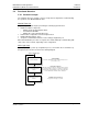
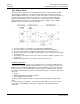
5.2.3 Normal Data Transfer
Normal data transfer includes the transferring of data received by, or to be transmitted to,
the master drivers and the status data. These data are transferred through read (input
image) and write (output image) blocks. Refer to Module Configuration for a description
of the data objects used with the blocks and the ladder logic required. The following
topics discuss the structure and function of each block.
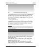
Read Block
These blocks of data transfer information from the module to the ControlLogix processor.
The structure of the input image used to transfer data received from the HART devices is
shown in the following table.
Offset Description Length
0 Reserved 1
1 Write Block ID 1
2 to 201 Read Data 200
202 to 248 Spare 47
249 Read Block ID 1
The Block Identification Code (word 249) signals the ControlLogix processor that a new
block is ready for processing and informs the processor of the contents of the block. If the
value of the code is set to 1, the block contains the first 200 words of data contained in
the database of the module.
If the Read Block ID is set to 0 or -1, the block contains the status data that should be
copied to the status data area in the module. This information can be used to determine
the "health" and activity of the module. Refer to Status Data Area and Error Codes for a
detailed listing of the area and its contents.
The normal read data block also contains the block identification code the module
expects to receive from the processor (word 1 in the block). Under normal data transfer
conditions, the ladder logic should use the code to build the appropriate block for the
module in the output image.