
User manual

1560-PDP
PROFIBUS – SCANport Adapter
11
Appendix A : Device Specific Hints
A.1 SMC Dialogue Plus
The SMC Dialogue Plus does not support Datalinks, therefore the configuration of SW2-
7 and 8 should not include any of the Datalinks Enabled. If a Datalink is enabled, the
SCANport Status LED will toggle, indicating an error in the SCANport communications.
The version of SMC which was tested (Rev 1.05) had 88 parameters. The 1560-PDP is
able to read 32 of the parameters out of the SMP3 unit.
A.2 SMP 3
The SMP3 does not support Datalinks, therefore the configuration of Datalinks should
not include any of the Datalinks Enabled. If a Datalink is enabled, the SCANport Status
LED will toggle, indicating an error in the SCANport communications. The 1560-PDP is
able to read 32 of the parameters out of the SMP3 unit.
A.3 Variable Speed Drives
In order to enable Frequency control from the 1560-PDP, the drive parameter
FREQUENCY SELECT 2 must be configured for the appropriate Adapter ID
representing the 1560-PDP module. This will normally be Adaptor #2, unless a
SCANport expander is being used (in which case this Adaptor number will be based on
the port the 1560-PDP is plugged into).
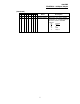
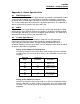
Setting up the Adaptor I/O - Datalinks Out
Selects the parameter values which will be made available from the 1560-PDP
via Global Data Out. Placement of the values in the 1560-PDP is referenced in
Section #
Data Out
Image
Suggested
Parameter
Description
A1
A2
54
1
Output Current
Output Volts
B1
B2
23
53
Output Power
DC Bus Voltage
C1
C2
D1
D2
19
4
Max Frequency
Last Fault
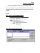
Setting up the Adaptor I/O - Data In
Selects the parameters which will be made accessible for configuration/ writing
from the 1560-PDP. As with the Data Out parameters, there are eight possible
selections. These may be chosen by the programmer to meet the needs of the
application.