
User manual

1560-PDP
PROFIBUS – SCANport Adapter
12
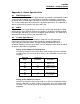
Logic Control Word
Since the most common implementation of the 1560-PDP is with the variable
speed drives, we have included the following table for the more commonly used
control bits. This word should be verified in the A-B User Manual for the particular
device being controlled.
Bit Function Description
0 Stop 1 = Stop, 0 = Not Stop
1 Start 1 = Start, 0 = Not Start
2 Jog 1 = Jog, 0 = Not Jog
3 Clear Faults 1 = Clear, 0 = Not Clear
4,5 Direction 00 = No Command
01 = Forward
10 = Reverse
11 = Hold Direction
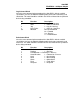
Drive Status Word
Since the most common implementation of the 1560-PDP is with the variable
speed drives, we have included the following table for the more commonly used
Status bits. This word should be verified in the A-B User Manual for the particular
device being monitored.
Bit Function Description
0 Enabled 1 = Enabled
1 Running 1 = Running
2 Cmd Direction 1 = Forward, 0 = Reverse
3 Actual Direction 1 = Forward, 0 = Reverse
4 Accel 1 = Accelerating
5 Decel 1 = Decelerating
6 Alarm 1 = Alarm Active
7 Fault 1 = Fault Active
8 At Speed 1 = At Speed