
User manual

1560-PDP
PROFIBUS – SCANport Adapter
Quick Start Guide
In this section we have assembled a simple step-by-step procedure for installing and
making the 1560-PDP unit operational. This discussion presumes that the application
decision such as PROFIBUS addressing and hierarchy, SCANport cable length, etc.
have been addressed prior to this point.
Step-by-Step
The following steps will allow the 1560-PDP to be setup in the shortest period of time
(the following steps refer to the Allen-Bradley drive implementation. Similar steps are
followed when interfacing to other A-B Power Division products):
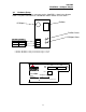
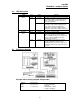
1 Set the dip switches
The 1560-PDP dip switch positions are detailed in Section 3.
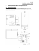
2 Mount the 1560-PDP on the DIN rail
See Section 3 for mounting instructions.
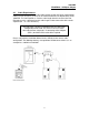
3 Connect power to the 1560-PDP
Refer to Section 3.
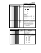
4 Setup the Drive hardware
Refer to the appropriate drive manual to connect control and power the
drive. This aspect of the drive installation is out of the scope of this
manual.
5 Setup the Drive parameters
See Appendix A of the manual for assistance in setup of the drive
parameters.
6 Install the SCANport cable between the drive and the 1560-PDP.
7 Connect the PROFIBUS cable between the host system and the
1560-PDP.
8 Retrieve the 1560-PDP GSD file, psft087c.gsd (downloadable from our
web site at www.prosoft-technology.com) and import into your
PROFIBUS configuration software.
9 Map the appropriate drive information and parameters to your addresses.
The User must configure the Siemens Profibus Binary file using a
Siemens compatible utility, importing the GSD file and configuring the I/O
image as desired. A minimum configuration would normally include the
Output Image(13 words) and the Input Image (11 words)
10 The unit will auto-baud once connected to the network