
User manual


1560-PDP
PROFIBUS – SCANport Adapter
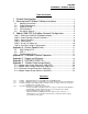
Table of Contents
1 Product Specifications ......................................................................................1
2 Mounting and SCANport Cabling Instructions........................................2
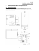
2.1 Mounting Instructions.......................................................................................2
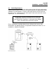
2.2 Cable Requirements ........................................................................................3
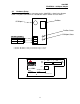
2.3 Hardware Setup................................................................................................4
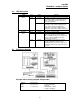
2.4 LED Indications.................................................................................................5
2.5 Dip Switch Settings ..........................................................................................5
3 Adding 1560-PDP to Profibus Network Configuration........................8
Step 1 : Select the 1560-PDPSCANport(Adapter)..................................................8
Step 2 : Select Configure Slave Parameters ...........................................................8
Step 3 : Select Configure ............................................................................................9
Step 4 : Parameterize ..................................................................................................9
Step 5 : Assign I/O Addresses .................................................................................10
Step 6 : Save the Profibus Configuration...............................................................10
Appendix A : Device Specific Hints...................................................................11
A.1 SMC Dialogue Plus ........................................................................................11
A.2 SMP 3...............................................................................................................11
A.3 Variable Speed Drives...................................................................................11
Appendix B : SCANport Datalink Operation..................................................13
Appendic C : Repair and Warranty....................................................................14
Appendix D : PSFT087C.GSD File ...................................................................15
Appendix E : Profibus Data Image Details ...................................................20
E.1 : Adapter Input Image (Read from 1560-PDP)...............................................20
E.2 : Adapter Status Image (Read from 1560-PDP).............................................21
E.3 : Parameters Image (Read from 1560-PDP)..................................................22
E.4 : Adapter Output Image (Write to 1560-PDP).................................................23
Revisions
1.0 2 8/25/98 Started with Revision 1.4 (6/30/98) of the 1560-MBP module.
1.1 3 12/7/98 Modified spare byte so that all data is on word boundary for input and output images
1.2 4 01/05/99 Attempt to get Profibus LED to respond to states of engine, and to get scanport to
fault when loss of Profibus exists
1.3 5 10/12/99 At Profibus Test Lab in Johnson City, TN
- Change Set Address handling to return no response - Did not have fully disabled
- Cfg handling on default. Did not have this set correctly where the default
actual and default to spc 3 were not equal
- added CommmTimeoutMultiplier based on SW2-1:3 (0 to 7) where 0 == 1
- added call to 0 ssa_buf_ptr after spc3 init because otherwise address change
generated a short response