
User manual

49TPTQ-104C ♦ 48TQuantum Platform Module Configuration
47TIEC 60870-5-104 Client
12TUser Manual
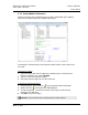
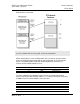
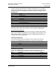
Write Register Count: 100
Note: The diagram above shows the memory addresses for a Quantum processor. If using a Unity
processor, substitute %MW for read only data, and %IW for read/write data.
Words 0 through 63 in each read/write block are reserved for special functions.
Refer to Command Control (Page 50) for more information on special function
blocks. The following table shows the relationship between the processor
memory and the module database areas.
Module Database
Register
Unity Register
Description
Read Data
3x
%IW
Input Register
Write Data
4x
%MW
Holding Register
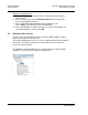
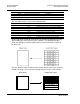
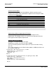
The data mapping in the following example shows the relationship between
processor and PTQ-104C memory addresses, assuming a 4x register start value
of 40001 and a PTQ-104C database start value of 0.
Processor Memory Address
Module Database Address
40065
0
40066
1
40067
2
40068
3
ProSoft Technology, Inc. Page 45 of 136
March 4, 2013