
User manual


49TPTQ-104C ♦ 48TQuantum Platform Diagnostics and Troubleshooting
47TIEC 60870-5-104 Client
12TUser Manual
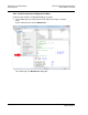
8.2 Diagnostics Menu
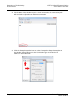
The Diagnostics menu in ProSoft Configuration Builder (PCB) for this module is
arranged as a tree structure, with the Main Menu at the top of the tree, and one
or more sub-menus for each menu command. The first menu displayed when
connected to the module is the Main menu.
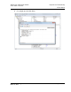
Because this is a text-based menu system, commands are entered by typing the
command letter from the computer keyboard in the Diagnostics window. The
module does not respond to mouse movements or clicks.
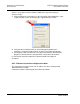
8.2.1 Required Hardware
There are two ways to connect the module with PCB – Serial or Ethernet.
When connecting serially to the module, ProSoft Technology recommends the
following minimum hardware to connect the computer to the module:
80486 based processor (Pentium preferred)
1 megabyte of memory
At least one UART hardware-based serial communications port available.
USB-based virtual UART systems (USB to serial port adapters) often do not
function reliably, especially during binary file transfers, such as when
uploading/downloading configuration files or module firmware upgrades.
Note: When connecting for the first time, a serial connection is required since the
IP address of the module has not been configured yet. Setting the IP address
of the module is detailed on page 19.
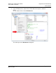
Once the IP address parameters have been configured in PCB and downloaded
(serially) to the module, PCB connectivity over Ethernet can be established.
ProSoft Technology, Inc. Page 95 of 136
March 4, 2013