
User manual

Configuring the Module PTQ-PDPMV1 ♦ Quantum Platform
User Manual PROFIBUS DP Master Network Interface Module for Quantum
Page 38 of 306 ProSoft Technology, Inc.
August 12, 2014
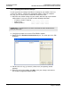
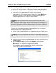
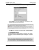
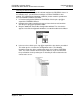
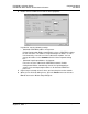
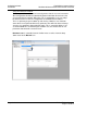
5 Drag the input and output parameters to the slot location grid below the Bus
Configuration window. This view displays the configuration data, order
number, and starting input and output addresses.
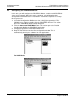
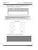
Important: The starting input and output addresses that you select here are actually byte offsets
within the PROFIBUS Data area inside each Input and Output backplane block.
For example, for the sample configuration for the input block, where the Input Start Register
Parameter = 1000:
The following table shows the actual Quantum address:
Input Address configured in PCB (Bytes)
Actual Quantum Input Register Address (Words)
0...1
301223
2...3
301224
4...5
301225
...
...