
Operating instructions

PTQ-MCM ♦ Quantum / Unity Platform Reference
Modbus Communication Module
Page 116 of 139 ProSoft Technology, Inc.
April 29, 2008
The following table is a sample read input status request to read inputs 10197 to
10218 from slave number 11.
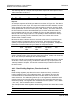
Adr Func Data Start Pt Hi Data Start Pt Lo Data #of Pts Hi Data #of Pts
Lo
Error Check Field
11 02 00 C4 00 16 CRC
Response
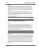
An example response to Read input status is as shown in Figure C4. The data is
packed one bit for each input. The response includes the slave address, function
code, quantity of data characters, the data characters, and error checking. Data
will be packed with one bit for each input (1=ON, 0=OFF). The lower order bit of
the first character contains the addressed input, and the remainder follow. For
input quantities that are not even multiples of eight, the last characters will be
filled in with zeros at high order end. The quantity of data characters is always
specified as a quantity of RTU characters, that is, the number is the same
whether RTU or ASCII is used.
Because the slave interface device is serviced at the end of a controller's scan,
data will reflect input status at the end of the scan. Some slaves will limit the
quantity of inputs provided each scan; thus, for large coil quantities, multiple PC
transactions must be made using coil status for sequential scans.
Adr Func Byte
Count
Data Discrete
Input 10197 to
10204
Data Discrete
Input 10205 to
10212
Data Discrete
Input 10213 to
10218
Error Check
Field
11 02 03 AC DB 35 CRC
The status of inputs 10197 to 10204 is shown as AC (HEX) = 10101 1100
(binary). Reading left to right, this show that inputs 10204, 10202, and 10199 are
all on. The other input data bytes are decoded similar.
Due to the quantity of input statuses requested, the last data field which is shown
as 35 HEX = 0011 0101 (binary) contains the status of only 6 inputs (10213 to
102180) instead of 8 inputs. The two left-most bits are provided as zeros to fill
the 8-bit format.
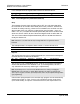
8.6.3 Read Holding Registers (Function Code 03)
Query
Read holding registers (03) allows the user to obtain the binary contents of
holding registers 4xxxx in the addressed slave. The registers can store the
numerical values of associated timers and counters which can be driven to
external devices. The addressing allows up to 125 registers to obtained at each
request; however, the specific slave device may have restriction that lower this
maximum quantity. The registers are numbered form zero (40001 = zero, 40002
= one, etc.). The broadcast mode is not allowed.
The example below reads registers 40108 through 40110 from slave 584 number
11.
Adr Func Data Start Reg Hi Data Start Reg Lo Data #of Regs Hi Data #of Regs Lo Error Check Field
11 03 00 6B 00 03 CRC