PTQ-LNG Quantum / Unity Platform Landis & Gyr Telegyr Interface Module User Manual May 29, 2007
Please Read This Notice Successful application of this module requires a reasonable working knowledge of the Schneider Electric Quantum / Unity hardware, the PTQ-LNG Module and the application in which the combination is to be used. For this reason, it is important that those responsible for implementation satisfy themselves that the combination will meet the needs of the application without exposing personnel or equipment to unsafe or inappropriate working conditions.
Contents PTQ-LNG ♦ Quantum / Unity Platform Landis & Gyr Telegyr Interface Module Contents PLEASE READ THIS NOTICE...........................................................................................................2 Important Notice:...........................................................................................................................2 Your Feedback Please ..................................................................................................................
PTQ-LNG ♦ Quantum / Unity Platform Landis & Gyr Telegyr Interface Module Contents 7 DIAGNOSTICS AND TROUBLESHOOTING........................................................................... 65 7.1 Reading Status Data From the Module ..................................................................... 65 7.1.1 The Configuration/Debug Menu .................................................................................. 65 7.1.2 Required Hardware .........................................................
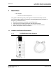
Start Here 1 PTQ-LNG ♦ Quantum / Unity Platform Landis & Gyr Telegyr Interface Module Start Here In This Chapter ¾ Hardware and Software Requirements .................................... 5 This guide is intended to guide you through the ProTalk module setup process, from removing the module from the box to exchanging data with the processor. In doing this, you will learn how to: 1.
PTQ-LNG ♦ Quantum / Unity Platform Landis & Gyr Telegyr Interface Module 1454-9F DB-9 Female to 5 Pos Screw Terminal Adapter (Serial protocol modules only) Start Here ProSoft Solutions CD Note: The DB-9 Female to 5 Pos Screw Terminal Adapter is not required on Ethernet modules and is therefore not included in the carton with these types of modules. Quantum / Unity Hardware This guide assumes that you are familiar with the installation and setup of the Quantum / Unity hardware.
Configuring the Processor with Concept 2 PTQ-LNG ♦ Quantum / Unity Platform Landis & Gyr Telegyr Interface Module Configuring the Processor with Concept In This Chapter ¾ Information for Concept Version 2.6 Users .............................. 7 ¾ Create a New Project ............................................................... 9 ¾ Add the PTQ Module to the Project........................................ 12 ¾ Set up Data Memory in Project ..............................................
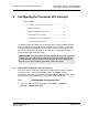
PTQ-LNG ♦ Quantum / Unity Platform Landis & Gyr Telegyr Interface Module Configuring the Processor with Concept This action opens the Concept Module Installation dialog box. 2 Choose File → Open Installation File. This action opens the Open Installation File dialog box: If you are using a Quantum processor, you will need the MDC files. In the File/Open dialog box, navigate to the MDC Files directory on the ProTalk CD. 4 Choose the MDC file and help file for your version of Concept: o Concept 2.
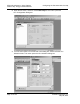
Configuring the Processor with Concept PTQ-LNG ♦ Quantum / Unity Platform Landis & Gyr Telegyr Interface Module Select the files that go with the Concept version you are using, and then click OK. This action opens the Add New Modules dialog box. Click the Add All button. A series of message boxes may appear during this process. Click Yes or OK for each message that appears. 6 When the process is complete, open the File menu and choose Exit to save your changes. 5 2.
PTQ-LNG ♦ Quantum / Unity Platform Landis & Gyr Telegyr Interface Module Configuring the Processor with Concept 2 Open the File menu, and then choose New Project. This action opens the PLC Configuration dialog box. 3 In tIn the list of options on the left side of this dialog box, double-click the PLC Selection folder. This action opens the PLC Selection dialog box. Page 10 of 103 ProSoft Technology, Inc.
Configuring the Processor with Concept PTQ-LNG ♦ Quantum / Unity Platform Landis & Gyr Telegyr Interface Module 4 In the CPU/Executive pane, use the scroll bar to locate and select the PLC to configure. 5 Click OK. This action opens the PLC Configuration dialog box, populated with the correct values for the PLC you selected. ProSoft Technology, Inc.
PTQ-LNG ♦ Quantum / Unity Platform Landis & Gyr Telegyr Interface Module 6 2.3 Configuring the Processor with Concept Make a note of the holding registers for the module. You will need this information when you modify your application as outlined in the ProTalk Application Reference Guides. The Holding Registers are displayed in the PLC Memory Partition pane of the PLC Configuration dialog box. Add the PTQ Module to the Project The next step is to add one or more of the PTQ modules to the Project.
Configuring the Processor with Concept PTQ-LNG ♦ Quantum / Unity Platform Landis & Gyr Telegyr Interface Module 2 Click the Edit button to open the Local Quantum Drop dialog box. This dialog box is where you identify rack and slot locations. 3 Click the Module button next to the rack/slot position where the ProTalk module will be installed. This action opens the I/O Module Selection dialog box. ProSoft Technology, Inc.
PTQ-LNG ♦ Quantum / Unity Platform Landis & Gyr Telegyr Interface Module Configuring the Processor with Concept 4 In the Modules pane, use the scroll bar to locate and select the ProTalk module, and then click OK. This action copies the description of the ProTalk module next to the assigned rack and slot number of the Local Quantum Drop dialog box. 5 Repeat steps 3 through 5 for each ProTalk module you plan to install.
Configuring the Processor with Concept 2.4 PTQ-LNG ♦ Quantum / Unity Platform Landis & Gyr Telegyr Interface Module Set up Data Memory in Project 1 In the list of options on the left side of the PLC Configuration dialog box, double-click Specials. 2 This action opens the Specials dialog box. ProSoft Technology, Inc.
PTQ-LNG ♦ Quantum / Unity Platform Landis & Gyr Telegyr Interface Module Configuring the Processor with Concept Selecting the Time of Day 3 Select (check) the Time of Day box, and then enter the value 00001 as shown in the following example. This value sets the first time of day register to 400001. 4 Click OK to save your settings and close the Specials dialog box. Saving your project 5 In the PLC Configuration dialog box, choose File -> Save project as. Page 16 of 103 ProSoft Technology, Inc.
Configuring the Processor with Concept 2.5 PTQ-LNG ♦ Quantum / Unity Platform Landis & Gyr Telegyr Interface Module 6 This action opens the Save Project As dialog box. 7 Name the project, and then click OK to save the project to a file. Download the Project to the Processor The next step is to download (copy) the project file to the Quantum Processor. 1 2 Use the null modem cable to connect your PC's serial port to the Quantum processor, as shown in the following illustration.
PTQ-LNG ♦ Quantum / Unity Platform Landis & Gyr Telegyr Interface Module 3 Configuring the Processor with Concept In the PLC Configuration dialog box, open the Online menu, and then choose Connect. This action opens the Connect to PLC dialog box. Leave the default settings as shown and click OK. Note: Click OK to dismiss any message boxes that appear during the connection process. 5 In the PLC Configuration window, open the Online menu, and then choose Download.
Configuring the Processor with Concept 2.6 PTQ-LNG ♦ Quantum / Unity Platform Landis & Gyr Telegyr Interface Module 6 Click All, and then click Download. If a message box appears indicating that the controller is running, click Yes to shut down the controller. The Download Controller dialog box displays the status of the download as shown in the following illustration. 7 When the download is complete, you will be prompted to restart the controller. Click Yes to restart the controller.
PTQ-LNG ♦ Quantum / Unity Platform Landis & Gyr Telegyr Interface Module Configuring the Processor with Concept 1 In the PLC Configuration window, open the Online menu, and then choose Online Control Panel. This action opens the Online Control Panel dialog box. 2 Click the Set Clock button to open the Set Controller's Time of Day Clock dialog box. Click the Write Panel button. This action updates the date and time fields in this dialog box.
Configuring the Processor with Concept 6 PTQ-LNG ♦ Quantum / Unity Platform Landis & Gyr Telegyr Interface Module Place the cursor over the first address field, as shown in the following illustration. In the PLC Configuration window, open the Templates menu, and then choose Insert Addresses. This action opens the Insert Addresses dialog box. 8 On the Insert Addresses dialog box, enter the values shown in the following illustration, and then click OK. 7 ProSoft Technology, Inc.
PTQ-LNG ♦ Quantum / Unity Platform Landis & Gyr Telegyr Interface Module 9 Configuring the Processor with Concept Notice that the template populates the address range, as shown in the following illustration. Place your cursor as shown in the first blank address field below the addresses you just entered. 10 Repeat steps 6 through 9, using the values in the following illustration: Page 22 of 103 ProSoft Technology, Inc.
Configuring the Processor with Concept PTQ-LNG ♦ Quantum / Unity Platform Landis & Gyr Telegyr Interface Module 11 In the PLC Configuration window, open the Online menu, and then choose Animate. This action opens the RDE Template dialog box, with animated values in the Value field. 12 Verify that values shown are cycling, starting from address 400008 on up. 13 In the PLC Configuration window, open the Templates menu, and then choose Save Template As.
PTQ-LNG ♦ Quantum / Unity Platform Landis & Gyr Telegyr Interface Module Page 24 of 103 Configuring the Processor with Concept ProSoft Technology, Inc.
Configuring the Processor with ProWORX 3 PTQ-LNG ♦ Quantum / Unity Platform Landis & Gyr Telegyr Interface Module Configuring the Processor with ProWORX When you use ProWORX 32 software to configure the processor, using the example SAF file provided on the ProTalk Solutions CD-ROM will be required.
PTQ-LNG ♦ Quantum / Unity Platform Landis & Gyr Telegyr Interface Module Configuring the Processor with ProWORX 3 Select the .SAF File that is located at the CD-ROM shipped with the PTQ module. 4 After you click on Open you should see the PTQ modules imported (select I/O series as Quantum): Page 26 of 103 ProSoft Technology, Inc.
Configuring the Processor with ProWORX PTQ-LNG ♦ Quantum / Unity Platform Landis & Gyr Telegyr Interface Module Now you can close the Schneider Alliances application and run the Proworx 32 software. At the Traffic Cop section, select the PTQ module to be inserted at the slot: ProSoft Technology, Inc.
PTQ-LNG ♦ Quantum / Unity Platform Landis & Gyr Telegyr Interface Module Page 28 of 103 Configuring the Processor with ProWORX ProSoft Technology, Inc.
Configuring the Processor with UnityPro XL 4 PTQ-LNG ♦ Quantum / Unity Platform Landis & Gyr Telegyr Interface Module Configuring the Processor with UnityPro XL In This Chapter ¾ Create a New Project ............................................................. 29 ¾ Add the PTQ Module to the Project........................................ 31 ¾ Build the Project ..................................................................... 32 ¾ Connect Your PC to the Processor ..............................
PTQ-LNG ♦ Quantum / Unity Platform Landis & Gyr Telegyr Interface Module Configuring the Processor with UnityPro XL 2 The next step is to add a power supply to the project. In the Project Browser, expand the Configuration folder, and then double-click the 1:LocalBus icon. This action opens a graphical window showing the arrangement of devices in your Quantum rack. 3 Select the rack position for the power supply, and then click the right mouse button to open a shortcut menu.
Configuring the Processor with UnityPro XL 4.2 PTQ-LNG ♦ Quantum / Unity Platform Landis & Gyr Telegyr Interface Module 4 Expand the Supply folder, and then select your power supply from the list. Click OK to continue. 5 Repeat these steps to add any additional devices to your Quantum Rack. Add the PTQ Module to the Project The next step is to add the PTQ module. 1 Expand the Communication tree, and select GEN NOM.
PTQ-LNG ♦ Quantum / Unity Platform Landis & Gyr Telegyr Interface Module 2 Configuring the Processor with UnityPro XL Next, enter the module personality value. The correct value for ProTalk modules is 1060 decimal (0424 hex). Before you can save the project in UnityProXL, you must validate the modifications. Open the Edit menu, and then choose Validate. If no errors are reported, you can save the project. 4 Save the project. 3 4.
Configuring the Processor with UnityPro XL 3 PTQ-LNG ♦ Quantum / Unity Platform Landis & Gyr Telegyr Interface Module As the project is built, Unity Pro XL reports its process in a Progress dialog box, with details appearing in a pane at the bottom of the window. The following illustration shows the build process under way. After the build process is completed successfully, the next step is to download the compiled project to the processor. 4.
PTQ-LNG ♦ Quantum / Unity Platform Landis & Gyr Telegyr Interface Module Configuring the Processor with UnityPro XL ¾ To verify address and driver settings in UnityPro XL: 1 Open the PLC menu, and choose Standard Mode. This action turns off the PLC Simulator, and allows you to communicate directly with the Quantum or Unity hardware. 2 Open the PLC menu, and choose Set Address... This action opens the Set Address dialog box.
Configuring the Processor with UnityPro XL PTQ-LNG ♦ Quantum / Unity Platform Landis & Gyr Telegyr Interface Module 4 Click the Driver Settings button to open the SCHNEIDER Drivers management Properties dialog box. 5 Click the Install/update button to specify the location of the Setup.exe file containing the drivers to use. You will need your UnityPro XL installation disks for this step. 6 Click the Browse button to locate the Setup.exe file to execute, and then execute the setup program.
PTQ-LNG ♦ Quantum / Unity Platform Landis & Gyr Telegyr Interface Module 4 Configuring the Processor with UnityPro XL Click the Test Connection button to verify that your settings are correct. The next step is to download the Project to the Processor. 4.5 Download the Project to the Processor Open the PLC menu and then choose Connect. This action opens a connection between the Unity Pro XL software and the processor, using the address and media type settings you configured in the previous step.
Setting Up the ProTalk Module 5 PTQ-LNG ♦ Quantum / Unity Platform Landis & Gyr Telegyr Interface Module Setting Up the ProTalk Module In This Chapter ¾ Install the ProTalk Module in the Quantum Rack ................... 37 ¾ Connect the PC to the ProTalk Configuration/Debug Port ..... 43 After you complete the following procedures, the ProTalk module will actively be transferring data bi-directionally with the processor. 5.1 Install the ProTalk Module in the Quantum Rack 5.1.
PTQ-LNG ♦ Quantum / Unity Platform Landis & Gyr Telegyr Interface Module 5.1.2 Setting Up the ProTalk Module Inserting the 1454-9F connector Insert the 1454-9F connector as shown. Wiring locations are shown in the table: 5.1.3 Install the ProTalk Module in the Quantum Rack Place the Module in the Quantum Rack. The ProTalk module must be placed in the same rack as the processor. 2 Tilt the module at a 45° angle and align the pegs at the top of the module with slots on the backplane.
Setting Up the ProTalk Module 3 PTQ-LNG ♦ Quantum / Unity Platform Landis & Gyr Telegyr Interface Module Push the module into place until it seats firmly in the backplane. CAUTION: The PTQ module is hot-swappable, meaning that you can install and remove it while the rack is powered up. You should not assume that this is the case for all types of modules unless the user manual for the product explicitly states that the module is hot-swappable.
PTQ-LNG ♦ Quantum / Unity Platform Landis & Gyr Telegyr Interface Module Setting Up the ProTalk Module RS-232 Configuration/Debug Port This port is physically a DB-9 connection. This port permits a PC based terminal emulation program to view configuration and status data in the module and to control the module.
Setting Up the ProTalk Module PTQ-LNG ♦ Quantum / Unity Platform Landis & Gyr Telegyr Interface Module RS-232 -- Modem Connection This type of connection is required between the module and a modem or other communication device. The "Use CTS Line" parameter for the port configuration should be set to 'Y' for most modem applications.
PTQ-LNG ♦ Quantum / Unity Platform Landis & Gyr Telegyr Interface Module Setting Up the ProTalk Module RS-232 -- Null Modem Connection (No Hardware Handshaking) This type of connection can be used to connect the module to a computer or field device communication port. NOTE: If the port is configured with the "Use CTS Line" set to 'Y', then a jumper is required between the RTS and the CTS line on the module connection. RS-485 The RS-485 interface requires a single two or three wire cable.
Setting Up the ProTalk Module PTQ-LNG ♦ Quantum / Unity Platform Landis & Gyr Telegyr Interface Module RS-422 RS-485 and RS-422 Tip If communication in the RS-422/RS-485 mode does not work at first, despite all attempts, try switching termination polarities. Some manufacturers interpret +/and A/B polarities differently. 5.2 Connect the PC to the ProTalk Configuration/Debug Port Make sure you have exited the Quantum programming software before performing these steps.
PTQ-LNG ♦ Quantum / Unity Platform Landis & Gyr Telegyr Interface Module Setting Up the ProTalk Module 3 In the HyperTerminal window, enter a connection name, for example Test, and then click OK. This action opens the Connect To dialog box. 4 In the Connect Using field, ensure that the com port matches the port on your PC to which you connected the Null Modem cable, and then click OK. This action opens the COMx Properties dialog box. Page 44 of 103 ProSoft Technology, Inc.
Setting Up the ProTalk Module PTQ-LNG ♦ Quantum / Unity Platform Landis & Gyr Telegyr Interface Module Verify that the settings match those shown in the example above, and then click OK. If your port settings are configured correctly, you will return to the HyperTerminal window. 6 In the HyperTerminal window, press [?]. This action opens the module's Configuration/Debug menu. 5 ProSoft Technology, Inc.
PTQ-LNG ♦ Quantum / Unity Platform Landis & Gyr Telegyr Interface Module Page 46 of 103 Setting Up the ProTalk Module ProSoft Technology, Inc.
Configuring the Module 6 PTQ-LNG ♦ Quantum / Unity Platform Landis & Gyr Telegyr Interface Module Configuring the Module In This Chapter 6.1 ¾ Before You Begin ................................................................... 47 ¾ Obtain the Sample Configuration Files................................... 48 ¾ Edit the Sample Configuration File Sections ..........................
PTQ-LNG ♦ Quantum / Unity Platform Landis & Gyr Telegyr Interface Module Configuring the Module 3 Browse to the configuration file on your PC and select it. Click Open. The configuration file appears in Notepad, ready for editing. 4 Edit the Sample Configuration File Sections Note: It is important that you plan your configuration before modifying the configuration files. The remainder of this step provides the information to make the appropriate modifications to the configuration files. 6.
Configuring the Module 5 PTQ-LNG ♦ Quantum / Unity Platform Landis & Gyr Telegyr Interface Module When Notepad starts, open the File menu, and then choose Open. Navigate to the folder where you copied the configuration file on your PC and select the file. Click Open. The configuration file will open in Notepad, ready for editing.
PTQ-LNG ♦ Quantum / Unity Platform Landis & Gyr Telegyr Interface Module Configuring the Module Module Type Parameter Module Type : PTQ-LNG The Module Type parameter is used to assign a name to the module that can be viewed using the configuration/debug port. Use this parameter to identify the module and the configuration file. You can enter a name from 0 to 80 characters.
Configuring the Module PTQ-LNG ♦ Quantum / Unity Platform Landis & Gyr Telegyr Interface Module Write Register Start Write Register Start : 0 #Database start register where data placed from #processor The Write Register Start parameter assigns the starting address for data to retrieve from the processor. Write Register Count Write Register Count : 600 #Number of registers to read from processor This parameter specifies the number of registers to be transferred from the module to the processor.
PTQ-LNG ♦ Quantum / Unity Platform Landis & Gyr Telegyr Interface Module Configuring the Module The Error/Status Block Pointer parameter is used to specify which database register the error and status data will be stored in. Refer to the chapter on Status Data Definition for more information. 6.3.3 [LNG Config] This section is used to define the LNG's configuration data.
Configuring the Module PTQ-LNG ♦ Quantum / Unity Platform Landis & Gyr Telegyr Interface Module SBO Timer Duration is multiplied by the Timer Base 0 = 10 milliseconds 1 = 100 milliseconds 2 = 1 second 3 = 10 seconds SBO Select Time : 0 #SBO Select Time (0-32767) SBO Time Select This is the time in milliseconds that a select is valid for an SBO port. This value is used for all SBO ports. 6.3.4 [LNG Port #] The following shows a sample LNG Port 1 section of the configuration file.
PTQ-LNG ♦ Quantum / Unity Platform Landis & Gyr Telegyr Interface Module Configuring the Module Stop Bits Stop Bits : 1 #1 or 2 stop bits for messages This parameter sets the number of stop bits to be used with each data value sent. Valid values are 1 or 2. RTS On RTS On : 50 #Delay after RTS set before message sent (mSec) This parameter sets the number of milliseconds to delay after RTS is asserted before the data will be transmitted. Valid values are 0 to 65535 milliseconds.
Configuring the Module 6.3.5 PTQ-LNG ♦ Quantum / Unity Platform Landis & Gyr Telegyr Interface Module [I/O Chassis] This section defines chassis. [I/O Chassis] indicates how many chassis have been used from [Chassis Number 0] to [Chassis Number 6]. Chassis numbers 1 through 6 follow the same format as the [Chassis Number 0] section.
PTQ-LNG ♦ Quantum / Unity Platform Landis & Gyr Telegyr Interface Module 6.3.6 Configuring the Module Special Functions Block 9992 – Select Before Operate If the module retrieves a BLOCK ID of 9992 from the PLC after it is issued the Command Function 22 by a master, it will place the SBO input data contained within the block into the event buffer and alter the data values for the points in the database.
Configuring the Module PTQ-LNG ♦ Quantum / Unity Platform Landis & Gyr Telegyr Interface Module Word Offset in Block Example Address Data Description 8 300108 Pulse Lower 100ms Control Control point Lower at 100ms 9 300109 Pulse Lower 100ms Pulse Lower at 100ms 10 300110 Pulse Raise 1s Control Control point Raise at 1s 11 300111 Pulse Raise 1s Pulse Raise at 1s 12 300112 Pulse Lower 1s Control Control point Lower at 1s 13 300113 Pulse Lower 1s Pulse Lower at 1s 14 300114 Puls
PTQ-LNG ♦ Quantum / Unity Platform Landis & Gyr Telegyr Interface Module Configuring the Module Block 9995 – Time Synchronization If the module retrieves a BLOCK ID of 9995 from the PLC after it is issued the Command Function 32 by a master, it will place the date and time data contained within the block into the event buffer and alter the data values for the points in the database.
Configuring the Module PTQ-LNG ♦ Quantum / Unity Platform Landis & Gyr Telegyr Interface Module Required Software In order to send and receive data over the serial port (COM port) on your computer to the module, you must use a communication program (terminal emulator). A simple communication program called HyperTerminal is pre-installed with recent versions of Microsoft Windows operating systems.
PTQ-LNG ♦ Quantum / Unity Platform Landis & Gyr Telegyr Interface Module Configuring the Module 2 Press [S] (Send Module Configuration). The message "Press Y key to confirm configuration send!" is displayed at the bottom of the screen. 3 Press [Y]. The screen now indicates that the module is ready to send. 4 From the Transfer menu in HyperTerminal, select Receive File. This action opens the Receive File dialog box. Page 60 of 103 ProSoft Technology, Inc.
Configuring the Module 5 PTQ-LNG ♦ Quantum / Unity Platform Landis & Gyr Telegyr Interface Module Use the Browse button to choose a folder on your computer to save the file, and then click Receive. • Note: ProSoft Technology suggests that you upload the configuration file preloaded on your module. However, configuration files are also available on the ProSoft CD as well as the ProSoft Technology web site at http://www.prosofttechnology.com. 6 Select Ymodem as the receiving protocol.
PTQ-LNG ♦ Quantum / Unity Platform Landis & Gyr Telegyr Interface Module 8 Configuring the Module The configuration file is now on your PC at the location you specified. You can now open and edit the file in a text editor such as Notepad. When you have finished editing the file, save it and close Notepad. Transferring the Configuration File to the Module Perform the following steps to transfer a configuration file from your PC to the module.
Configuring the Module PTQ-LNG ♦ Quantum / Unity Platform Landis & Gyr Telegyr Interface Module 3 Press [Y]. The screen now indicates that the PC is ready to send. 4 From the Transfer menu in HyperTerminal, select Send File. The Send File dialog appears. 5 Use the Browse button to locate the configuration file your computer. Note: This procedure assumes that you are uploading a newly edited configuration file from your PC to the module.
PTQ-LNG ♦ Quantum / Unity Platform Landis & Gyr Telegyr Interface Module 6 7 Configuring the Module Select Ymodem as the protocol. Click the Send button. This action opens the Ymodem File Send dialog box. When the file transfer is complete, the module's configuration/debug screen indicates that the module has reloaded program values, and displays information about the module. 8 Your module now contains the new configuration. Page 64 of 103 ProSoft Technology, Inc.
Diagnostics and Troubleshooting 7 PTQ-LNG ♦ Quantum / Unity Platform Landis & Gyr Telegyr Interface Module Diagnostics and Troubleshooting In This Chapter ¾ Reading Status Data From the Module .................................. 65 ¾ LED Status Indicators ............................................................ 79 The module provides information on diagnostics and troubleshooting in the following forms: 7.1 Status data values are transferred from the module to the processor.
PTQ-LNG ♦ Quantum / Unity Platform Landis & Gyr Telegyr Interface Module Diagnostics and Troubleshooting The organization of the menu structure is represented in simplified form in the following illustration: The remainder of this section shows you the menus available for this module, and briefly discusses the commands available to you. Keystrokes The keyboard commands on these menus are almost always non-case sensitive. You can enter most commands in lower case or capital letters.
Diagnostics and Troubleshooting PTQ-LNG ♦ Quantum / Unity Platform Landis & Gyr Telegyr Interface Module communication program. The following table lists communication programs that have been tested by ProSoft Technology. DOS ProComm, as well as several other terminal emulation programs Windows 3.1 Terminal Windows 95/98 HyperTerminal Windows NT/2000/XP HyperTerminal The module uses the Ymodem file transfer protocol to send (upload) and receive (download) configuration files from your module.
PTQ-LNG ♦ Quantum / Unity Platform Landis & Gyr Telegyr Interface Module 7.1.5 Diagnostics and Troubleshooting Main Menu When you first connect to the module from your computer, your terminal screen will be blank. To activate the main menu, press the [?] key on your computer's keyboard.
Diagnostics and Troubleshooting PTQ-LNG ♦ Quantum / Unity Platform Landis & Gyr Telegyr Interface Module disable the data analyzer. This action will allow the module to resume its normal operating mode. Viewing Block Transfer Statistics Press [B] from the Main Menu to view the Block Transfer Statistics screen. Use this command to display the configuration and statistics of the backplane data transfer operations between the module and the processor.
PTQ-LNG ♦ Quantum / Unity Platform Landis & Gyr Telegyr Interface Module Diagnostics and Troubleshooting Press [Y] to confirm the file transfer, and then follow the instructions on the terminal screen to complete the file transfer process. After the file has been successfully downloaded, you can open and edit the file to change the module's configuration. Viewing Version Information Press [V] to view Version information for the module.
Diagnostics and Troubleshooting PTQ-LNG ♦ Quantum / Unity Platform Landis & Gyr Telegyr Interface Module Exiting the Program Caution: Some of the commands available to you from this menu are designed for advanced debugging and system testing only, and can cause the module to stop communicating with the processor or with other devices, resulting in potential data loss or other failures. Only use these commands if you are specifically directed to do so by ProSoft Technology Technical Support staff.
PTQ-LNG ♦ Quantum / Unity Platform Landis & Gyr Telegyr Interface Module Diagnostics and Troubleshooting And so on. The total number of register pages available to view depends on your module's configuration. Displaying the Current Page of Registers Again This screen displays the current page of 100 registers in the database. Moving Back Through 5 Pages of Registers Press [-] from the Database View menu to skip back to the previous 500 registers of data.
Diagnostics and Troubleshooting PTQ-LNG ♦ Quantum / Unity Platform Landis & Gyr Telegyr Interface Module Returning to the Main Menu Press [M] to return to the Main Menu. 7.1.7 Backplane Menu Press [B] from the Main Menu to view the Backplane Data Exchange List. Use this command to display the configuration and statistics of the backplane data transfer operations. Press [?] to view a list of commands available on this menu. Redisplaying the Menu Press [?] to display the current menu.
PTQ-LNG ♦ Quantum / Unity Platform Landis & Gyr Telegyr Interface Module Diagnostics and Troubleshooting Viewing Backplane Diagnostic Information Press [D] to view Backplane Diagnostic information. Use this command to display the configuration and statistics of the backplane data transfer operations between the module and the processor. The information on this screen can help determine if there are communication problems between the processor and the module.
Diagnostics and Troubleshooting PTQ-LNG ♦ Quantum / Unity Platform Landis & Gyr Telegyr Interface Module Important: When in analyzer mode, program execution will slow down. Only use this tool during a trouble-shooting session. Before disconnecting from the Config/Debug port, please be sure to press [M] to return to the main menu and disable the data analyzer. This action will allow the module to resume its normal operating mode.
PTQ-LNG ♦ Quantum / Unity Platform Landis & Gyr Telegyr Interface Module Diagnostics and Troubleshooting Viewing Data in Hexadecimal Format Press [H] to display the data on the current page in hexadecimal format. Viewing Data in ASCII (Text) Format Press [A] to display the data on the current page in ASCII format. This is useful for regions of the database that contain ASCII data. Starting the Data Analyzer Press [B] to start the data analyzer.
Diagnostics and Troubleshooting PTQ-LNG ♦ Quantum / Unity Platform Landis & Gyr Telegyr Interface Module before returning to the main menu or disconnecting from the port. This action will allow the module to resume its normal operating mode. Returning to the Main Menu Press [M] to return to the Main Menu. 7.1.9 Data Analyzer Tips From the main menu, press [A] for the "Data Analyzer".
PTQ-LNG ♦ Quantum / Unity Platform Landis & Gyr Telegyr Interface Module Diagnostics and Troubleshooting After you have selected the Port, Format, and Tick, we are now ready to start a capture of this data. The easiest way to do so is to go up to the top of you HyperTerminal window, and do a Transfer -> Capture Text as shown below: After selecting the above option, the following window will appear: Next name the file, and select a directory to store the file in.
Diagnostics and Troubleshooting PTQ-LNG ♦ Quantum / Unity Platform Landis & Gyr Telegyr Interface Module The means that the module is transitioning the communications line to a transmit state. All characters shown in <> brackets are characters being sent out by the module. The shows when the module is done transmitting data, and is now ready to receive information back. And finally, all characters shown in the [ ] brackets is information being received from another device by the module.
PTQ-LNG ♦ Quantum / Unity Platform Landis & Gyr Telegyr Interface Module Diagnostics and Troubleshooting ProTalk Module Color Status Indication Active Green On The LED is on when the module is recognizes a processor and is able to communicate if the [Backplane Data Movement] section specifies data transfer commands. Off The LED is off when the module is unable to speak with the processor. The processor either absent or not running. Off The battery voltage is OK and functioning.
Reference 8 PTQ-LNG ♦ Quantum / Unity Platform Landis & Gyr Telegyr Interface Module Reference In This Chapter 8.1 ¾ Product Specifications............................................................ 81 ¾ PTQ-LNG Functionality Overview .......................................... 83 ¾ Configuration Data Definition ................................................. 86 ¾ PTQ-LNG Status Data Definition............................................ 87 ¾ PTQ-LNG Command Descriptions ....................
PTQ-LNG ♦ Quantum / Unity Platform Landis & Gyr Telegyr Interface Module Reference Up to six modules can be placed in a rack Local rack – The module must be placed in the same rack as processor. Compatible with common Quantum / Unity programming tools. o UnityPro XL o Concept o ProWORX Quantum data types supported: 3x, 4x High speed data transfer across backplane provides quick data update times. Sample ladder file available. 8.1.
Reference PTQ-LNG ♦ Quantum / Unity Platform Landis & Gyr Telegyr Interface Module o o Accumulators: 50 points Indication Points: 800 points Supported Function Codes 8.
PTQ-LNG ♦ Quantum / Unity Platform Landis & Gyr Telegyr Interface Module 8.2.1 Reference General Concepts The following discussion explains several concepts that are important for understanding the operation of the PTQ-LNG module. Module Power Up On power up, the module begins performing the following logical functions: 1 Read configuration for module from LNGS.
Reference PTQ-LNG ♦ Quantum / Unity Platform Landis & Gyr Telegyr Interface Module PTQ-LNG Database Map The following table shows the layout of the database.
PTQ-LNG ♦ Quantum / Unity Platform Landis & Gyr Telegyr Interface Module Start Address End Address 2035 2036 2051 2052 2053 2068 2069 2070 2085 2086 2087 2102 2103 2104 2119 5000 Reference Data Quantum Address Chassis Number 2 Internal Only Card Code Internal Only Chassis Number 3 Internal Only Card Code Internal Only Chassis Number 4 Internal Only Card Code Internal Only Chassis Number 5 Internal Only Card Code Internal Only Chassis Number 6 Internal Only Card Code Intern
Reference PTQ-LNG ♦ Quantum / Unity Platform Landis & Gyr Telegyr Interface Module Register Range Parameter 5013 5 to 8 Port 1 Data Bits 5014 1, 2 Port 1 Stop Bits 5015 0 to 65535 Port 1 RTS On (mSec) 5016 0 to 65535 Port 1 RTS Off (mSec) 5017 0 to 65535 Port 1 Minimum Response Delay (mSec) 5018 0, 1 Port 1 Use CTS (Y, N) 5019 0 to 255 Port 1 Slave ID 5030 0, 1 Port 2 Enable 5031 8.
PTQ-LNG ♦ Quantum / Unity Platform Landis & Gyr Telegyr Interface Module Reference Register Content Description 6014 Number of responses - Port 2 Contains the total number of messages sent out of the port. 6015 Number of errors sent - Port 2 Contains the total number of message errors sent out the port. 6016 Number of errors received Port 2 Contains the total number of message errors received on the port.
Reference PTQ-LNG ♦ Quantum / Unity Platform Landis & Gyr Telegyr Interface Module Command Command Description ADC Reference Force Report - 5 This command returns hardcoded values to the host for one ADC point. The following values are returned for the -90%, 0% and 90% respectively, 205, 2048, and 3890. Indication Change Report - 6 This command returns the status and memory bit values for the indication points that have had a change since the last host request.
PTQ-LNG ♦ Quantum / Unity Platform Landis & Gyr Telegyr Interface Module Reference Command Command Description Accumulator Change Report - 12 This command is implemented in the module per the protocol specification. Up to 50 accumulators are supported by the module. This command returns the last frozen value for each accumulator if the freeze flag is set. Use Function 26 to set the freeze flag. The freeze flag is reset by this function.
Reference 8.6 PTQ-LNG ♦ Quantum / Unity Platform Landis & Gyr Telegyr Interface Module Command Command Description Analog Group Defines - 35 This command is implemented per the protocol specification. Up to 300 analog values are supported by the module. Accumulator Preset - 36 This command is implemented in the module per the protocol specification. Up to 50 preset values are supported by the module. The RTU presets the running values of selected accumulators to the specified 16 bit values.
PTQ-LNG ♦ Quantum / Unity Platform Landis & Gyr Telegyr Interface Module Reference SHR: Short Response flag is set if the message does not contain any data blocks. RTU Address: The RTU address specifies the receiving RTU for the message. There is one byte for the RTU address allowing the master station to address 255 distinctive RTU's. An address of 0 is used for a broadcast message. 8.6.
Reference PTQ-LNG ♦ Quantum / Unity Platform Landis & Gyr Telegyr Interface Module 8.6.4 RTU Message Header 7 6 5 4 3 2 1 0 SHR CON FRZ IND SCH SLG 0 0 RTU ADDRESS The RTU Message Header consisted of two characters. The first character contains several RTU flags. The second character contains the address of the responding RTU. SHR: Short Response flag is set if the Message does not contain any Data Block.
PTQ-LNG ♦ Quantum / Unity Platform Landis & Gyr Telegyr Interface Module Reference L: The Last Block Mark is always set to one in the last Data Block of the messages, else it is reset to 0. Function Code: The function code is a 7 bit field that defines the purpose of the message. The RTU generally echoes the function code sent by the Master, except when the RTU cannot perform the requested function due to an error, timeout, bad parameter, or some other condition that is not logical to the RTU.
Reference 8.7.5 PTQ-LNG ♦ Quantum / Unity Platform Landis & Gyr Telegyr Interface Module Does the module work in a remote rack? The module is designed to be located in the chassis with the PLC and will not operate in a remote chassis. If your application requires remote placement of the communication device you should investigate the other members of the ProLinx family such as the 4202-MNET-DFCM.
PTQ-LNG ♦ Quantum / Unity Platform Landis & Gyr Telegyr Interface Module Page 96 of 103 Reference ProSoft Technology, Inc.
Reference PTQ-LNG ♦ Quantum / Unity Platform Landis & Gyr Telegyr Interface Module Support, Service & Warranty ProSoft Technology, Inc. survives on its ability to provide meaningful support to its customers. Should any questions or problems arise, please feel free to contact us at: Internet Web Site: http://www.prosoft-technology.com/support E-mail address: support@prosoft-technology.com Phone +1 (661) 716-5100 +1 (661) 716-5101 (Fax) Postal Mail ProSoft Technology, Inc.
PTQ-LNG ♦ Quantum / Unity Platform Landis & Gyr Telegyr Interface Module Reference General Warranty Policy – Terms and Conditions ProSoft Technology, Inc. (hereinafter referred to as ProSoft) warrants that the Product shall conform to and perform in accordance with published technical specifications and the accompanying written materials, and shall be free of defects in materials and workmanship, for the period of time herein indicated, such warranty period commencing upon receipt of the Product.
Reference PTQ-LNG ♦ Quantum / Unity Platform Landis & Gyr Telegyr Interface Module Warranty Procedure: Upon return of the hardware product ProSoft will, at its option, repair or replace the product at no additional charge, freight prepaid, except as set forth below. Repair parts and replacement product will be furnished on an exchange basis and will be either reconditioned or new. All replaced product and parts become the property of ProSoft.
PTQ-LNG ♦ Quantum / Unity Platform Landis & Gyr Telegyr Interface Module Page 100 of 103 Reference ProSoft Technology, Inc.
Index PTQ-LNG ♦ Quantum / Unity Platform Landis & Gyr Telegyr Interface Module Create a New Project • 9, 29 Index [ [Backplane Configuration] • 50 [I/O Chassis] • 55 [LNG Config] • 52 [LNG Port #] • 53 [Module] • 49 3 D Data Analyzer • 74 Data Analyzer Tips • 77 Data Bits • 53 Database View Menu • 71 Diagnostics and Troubleshooting • 65 Digital Input Count • 52 Displaying the Current Page of Registers Again • 72 Displaying Timing Marks in the Data Analyzer • 75 Does the module work in a remote rack? • 9
PTQ-LNG ♦ Quantum / Unity Platform Landis & Gyr Telegyr Interface Module K Keystrokes • 66 L LED Status Indicators • 79 LNG Message Format • 91 M Main Logic Loop • 84 Main Menu • 68 Master CRC • 92 Master Data Block • 92 Master Message Header • 91 Minimum Command Delay • 54 Module Control Blocks • 86 Module Name Parameter • 50 Module Power Up • 84 Module Type Parameter • 50 Moving Back Through 5 Pages of Registers • 72 N Navigation • 65 O Obtain the Sample Configuration Files • 48 Opening the Backplane
Index PTQ-LNG ♦ Quantum / Unity Platform Landis & Gyr Telegyr Interface Module Viewing Backplane Diagnostic Information • 74 Viewing Block Transfer Statistics • 69 Viewing Configuration Information • 73 Viewing Data in ASCII (Text) Format • 72, 76 Viewing Data in Decimal Format • 72 Viewing Data in Floating Point Format • 72 Viewing Data in Hexadecimal Format • 72, 76 Viewing Module Configuration • 69 Viewing Port Communication Status • 70 Viewing Port Configuration • 70 Viewing Register Pages • 71 Viewing