
User manual

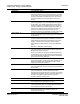
Table Of Contents
- Start Here
- Configuring the Processor with Concept
- Configuring the Processor with ProWORX
- Configuring the Processor with UnityPro XL
- To build (compile) the project:
- To verify address and driver settings in UnityPro XL:
- Setting Up the ProTalk Module
- Configuring the Module
- Diagnostics and Troubleshooting
- Reading Status Data From the Module
- The Configuration/Debug Menu
- Required Hardware
- Required Software
- Using the Configuration/Debug Port
- Main Menu
- Opening the Data Analyzer Menu
- Viewing Block Transfer Statistics
- Viewing Module Configuration
- Opening the Database Menu
- Opening the Backplane Menu
- Transferring the Configuration File from PC to PTQ module
- Transferring the Configuration File from PTQ module to PC
- Viewing Version Information
- Warm Booting the Module
- Viewing Port Communication Status
- Viewing Port Configuration
- Exiting the Program
- Database View Menu
- Viewing Register Pages
- Displaying the Current Page of Registers Again
- Moving Back Through 5 Pages of Registers
- Viewing the Previous 100 Registers of Data
- Skipping 500 Registers of Data
- Viewing the Next 100 Registers of Data
- Viewing Data in Decimal Format
- Viewing Data in Hexadecimal Format
- Viewing Data in Floating Point Format
- Viewing Data in ASCII (Text) Format
- Returning to the Main Menu
- Backplane Menu
- Data Analyzer
- Data Analyzer Tips
- LED Status Indicators
- Reading Status Data From the Module
- Reference
- Index

PTQ-LNG ♦ Quantum / Unity Platform Reference
Landis & Gyr Telegyr Interface Module
Page 90 of 103 ProSoft Technology, Inc.
May 29, 2007
Command Command Description
Accumulator Change Report - 12
This command is implemented in the module per the
protocol specification. Up to 50 accumulators are supported
by the module. This command returns the last frozen value
for each accumulator if the freeze flag is set. Use Function
26 to set the freeze flag. The freeze flag is reset by this
function.
Accumulator Force Report - 13
This command is implemented in the module per the
protocol specification. Up to 50 accumulators are supported
by the module. The module reports the last frozen value for
each accumulator in the specified range. If the stop point
number is greater than the largest actual point number, only
values for the actual points are returned. If the stop point
number is less than the start point number, an error
message is returned. The freeze flag is reset by this function.
Analog Output - 20
This command is implemented in the module per the
protocol specification. Up to 50 analog values are supported
by the module.
SBO Select - 21
When an SBO select command is received from the host,
the point is selected and the timer is started. The point will
remain selected until the point is operated upon, the timer
expires, or another point is selected. The select time is
determined by the SBO Duration value and the SBO Base
value.
SBO Time = SBO Base * SBO Duration.
SBO Operate - 22
The SBO Operate command will cause a previously selected
point to be operated. An error response will be generated if
the point has not been selected.
There is no real limit on the number of SBO points that can
be addressed by the host. The ladder logic implemented as
part of the application will determine if a write command will
move into the processor data table.
Digital Output - 23
This command is implemented in the module per the
protocol specification, except that the upper 8 bits of the 24
bit write are disregarded. This allows 50 words of 16 bit
digital output data to be addressed.
Accumulator Freeze - 24
This command is implemented in the module per the
protocol specification. Up to 50 analog values are supported
by the module.
Pulse Output - 25
This command is implemented in the module per the
protocol specification. The module decodes the write
command and moves the data to the processor in a series of
data structures depending on the type and time base of the
command. Through these data structures, support is
provided to address 9 pulse points.
Pulse Train Output - 26 (Hold) This command is not implemented at this time.
Restart RTU - 30
This command is implemented in the module per the
protocol specification, performing a cold boot.
RTU Configuration - 31
This command is implemented in the module to support one
rack of configuration data. The configuration data is moved
to the module with a write to the M1 file.
Analog Deadbands - 34
This command is implemented in the module per the
protocol specification. Up to 300 analog values are
supported by the module.