
User manual
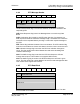


Table Of Contents
- Start Here
- Configuring the Processor with Concept
- Configuring the Processor with ProWORX
- Configuring the Processor with UnityPro XL
- To build (compile) the project:
- To verify address and driver settings in UnityPro XL:
- Setting Up the ProTalk Module
- Configuring the Module
- Diagnostics and Troubleshooting
- Reading Status Data From the Module
- The Configuration/Debug Menu
- Required Hardware
- Required Software
- Using the Configuration/Debug Port
- Main Menu
- Opening the Data Analyzer Menu
- Viewing Block Transfer Statistics
- Viewing Module Configuration
- Opening the Database Menu
- Opening the Backplane Menu
- Transferring the Configuration File from PC to PTQ module
- Transferring the Configuration File from PTQ module to PC
- Viewing Version Information
- Warm Booting the Module
- Viewing Port Communication Status
- Viewing Port Configuration
- Exiting the Program
- Database View Menu
- Viewing Register Pages
- Displaying the Current Page of Registers Again
- Moving Back Through 5 Pages of Registers
- Viewing the Previous 100 Registers of Data
- Skipping 500 Registers of Data
- Viewing the Next 100 Registers of Data
- Viewing Data in Decimal Format
- Viewing Data in Hexadecimal Format
- Viewing Data in Floating Point Format
- Viewing Data in ASCII (Text) Format
- Returning to the Main Menu
- Backplane Menu
- Data Analyzer
- Data Analyzer Tips
- LED Status Indicators
- Reading Status Data From the Module
- Reference
- Index
PTQ-LNG ♦ Quantum / Unity Platform Reference
Landis & Gyr Telegyr Interface Module
Page 92 of 103 ProSoft Technology, Inc.
May 29, 2007
SHR: Short Response flag is set if the message does not contain any data
blocks.
RTU Address: The RTU address specifies the receiving RTU for the message.
There is one byte for the RTU address allowing the master station to address
255 distinctive RTU's. An address of 0 is used for a broadcast message.
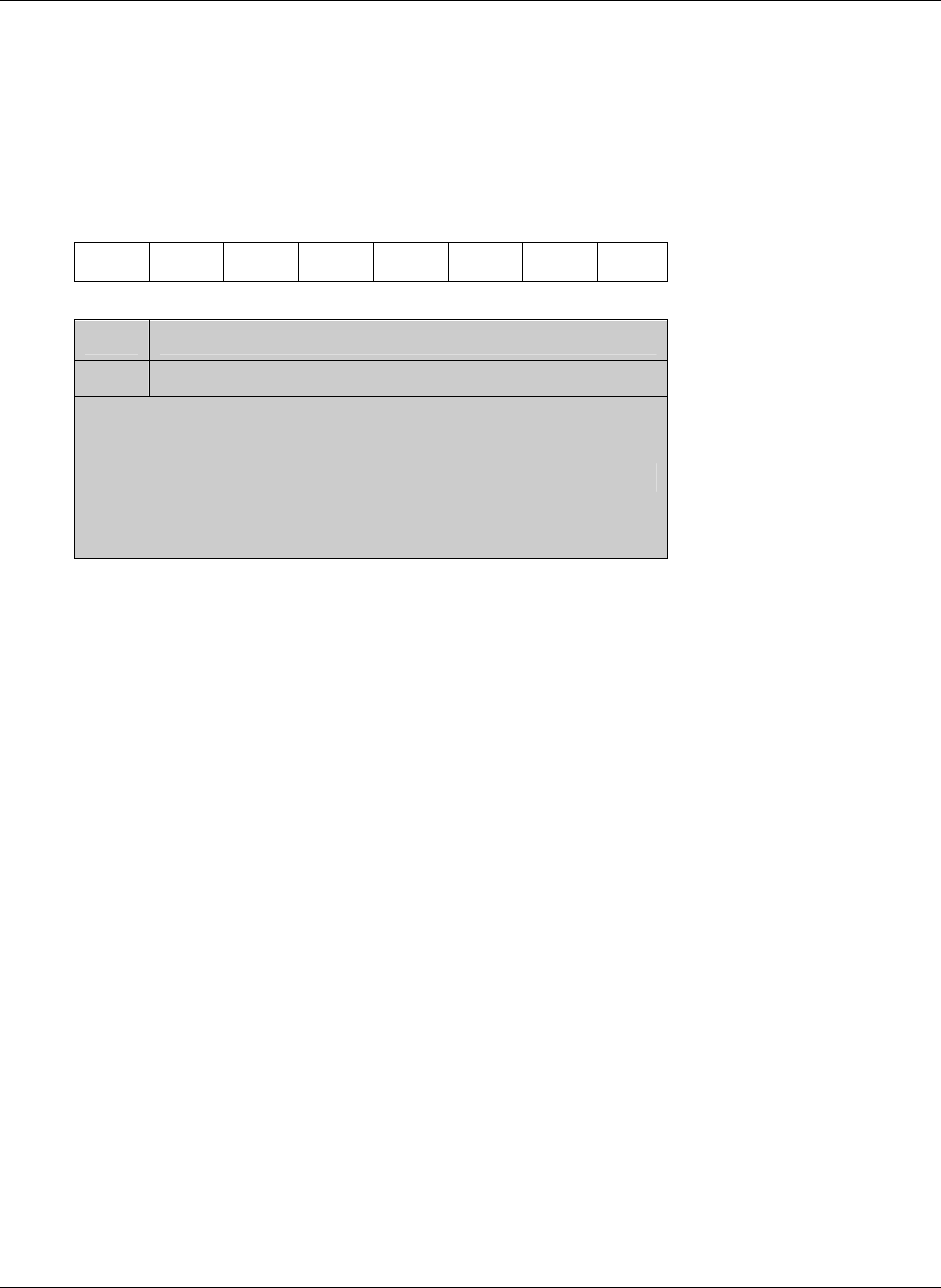
8.6.2 Master Data Block
7 6 5 4 3 2 1 0
L FUNCTION CODE
0 LENGTH
DATA FIELD
A master originated message can contain only one data block. The data block
consists of four fields:
L: The Last Block Mark is always set to one in master originated messages.
Function Code: The function code is a 7 bit field that defines the function to be
performed by the RTU.
Length: The Length is a 7 bit field specifying the number of bytes in the Data
Field. If it is 0, then the Data Block does not contain a Data Field.
Data Field: The Data Field contain Function Code specific operational
information (that is, point numbers, parameters, etc.)
8.6.3 Master CRC
The CRC code included in the message is the standard CRC16 based on the
polynomial. For a correctly received message the remainder will be zero after
passing the entire message, including the CRC word, through the CRC
computation. The bits of each message byte are passed through the CRC
computation in the same order that they are transmitted, least significant bit first.