manuale di istruzioni instructions manual 1^ edizione Settembre 2005 1st edition September 2005
ProSpot 575 MB numero di serie/serial number data di acquisto/date of purchase fornitore/retailer indirizzo/address cap/città/suburb provincia/capital city stato/state tel./fax/ Prendete nota, nello spazio apposito, dei dati relativi al modello e al rivenditore del vostro ProSpot 575 MB: in caso di richiesta di informazioni, pezzi di ricambio, servizi di riparazione o altro ci permetteranno di assistervi con la massima rapidità e precisione.
English Index 1. Packaging and transportation Pag. 4 1.1. Packaging 1.2. Transportation “ “ 2. General information 4 4 Pag. 4 2.1. Important safety information 2.2. Warranty conditions 2.3. CE norms “ “ “ 3. Product specifications 4 5 5 Pag. 5 3.1. Technical characteristics 3.2. Dimensions 3.3. Projector components “ “ “ 4. Installation 5 5 5 Pag. 6 4.1. Mechanical installation 4.2. Safety connections “ “ 5. Powering up 6 6 Pag. 7 5.1. Operating voltage and frequency 5.2.
English Congratulations on having purchased a coemar product. You have assured yourself of a fixture of the highest quality, both in componentry and in the technology used. We renew our invitation to you to complete the service information on the previous page, to expedite any request for service information or spares (in case of problems encountered either during, or subsequent to, installation). This information will assist in providing prompt and accurate advice from your coemar service centre. 1.
English 2.2. Warranty conditions 1. The fixture is guaranteed for a period of 12 months from the date of purchase against manufacturing or materials defects 2. The warranty does not extend to damage caused by inappropriate usage or use by inexperienced operators. 3. The warranty is immediately void if the projector has been operated or dismantled by unauthorised personnel 4. The warranty does not extend to fixture replacement 5.
English 4. Installation 4.1. Mechanical installation ProSpot 575 MB may be either floor or ceiling mounted. For floor mounting, the unit is provided with four rubber mounting feet. For ceiling mounted installations, Coemar includes two cam-lock (A) support brackets. The two cam-lock brackets may be mounted in two different positions (B & C) on the base of the ProSpot 575 MB. The cam-lock brackets are affixed via a 1/4 nut. Please ensure that they are correctly seated and firmly tightened into position.
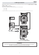
English 5. Powering up 5.1. Operating voltage and frequency The projector may operate at voltages of 208, 230 or 240VAC at a frequency of 50 or 60Hz. Coemar presets (barring specific requests) a voltage of 240v at a frequency of 50Hz.. The preset voltage is indicated on the base of the projector. factory set main at: 100V 115V 208V 230V 240V 50Hz 60Hz 5.2.
English Locate the lamp ballast inside the base. Select a voltage from amongst 208, 230 or 240V by disconnecting cable n° 8 and moving it to the correct voltage. Select a frequency from amongst 50 or 60Hz by disconnecting cable n° 13 and moving it to the correct frequency. Refer to the sticker located on the ballast to ensure the proper terminals are selected for your requriements. When you have made changes, note these on the outside of the ProSpot 575 MB.
English 6. DMX signal connection Control signal is digital and is transmitted via two pair screened ø0.5mm cable as per international standards for the transmission of DMX512 data. Connection is serial, utilising XLR 3 male and female sockets located on the base of the ProSpot 575 MB, labeled DMX 512 IN and OUT (see diagram).
English 7. Turning on the projector After having followed the preceding steps, turn on the projector via the main Power switch. The display and will show in sequnece the software version installed in the 3 onboard microprocessors - the display master “A” and “B”. For example, upon turning on power, the ProSpot 575 MB may show: D1.02 A1.03 B 1.
English 7.2.
English channel 13 function gobo rotation on wheel 1 and fine indexing control type of control 101 - 176 40% - 69% gobo stop 177 - 179 69% - 70% continuous rotation of the gobo in a clockwise direction with a proportional increase in speed 180 - 255 71% - 100% step step or proportional selectable via channel 20 nogobo 0 11 - 40 41 - 70 4% - 16% 16% - 27% gobo 3 gobo 4 71 - 100 101 - 130 28% - 39% 40% - 51% gobo 5 gobo 6 131 - 160 161 - 192 51% - 63% 63% - 75% continuous rotation of the
English 8. Display panel functions The display panel of the ProSpot 575 MB shows all the functions available; it is possible to change some of those parameters and to add some functions. Changing the preset settings made by Coemar can vary the functions of the device so that it may not respond to a DMX 512 controller being used to control it. Carefully follow the instructions before applying any variations or selections. NOTE: the symbol ☞ shows which key has to be pushed to obtain the desired function .
English 8.2. Measure and test (MEAS) The internal microprocessor of the ProSpot 575 MB allows for several diagnostic and output parameters to be displayed. You may record, in this menu, determine the position in which the projector will come to rest when turned on with no dmx signal attached.
English 8.3. Function settings (FUNC) The projector allows the altering of several functions and for selecting personalised settings. AOO1 ☞ +o– ☞ menu MEAS ☞ +o– A 0 23 DMX address 23 select new DMX address ☞ enter A 0 23 new DMX address F U NC ☞ enter ☞ +o– ☞ +o– ☞ +o– ☞ +o– ☞ +o– ☞ +o– PDIR ☞ TDIR ☞ +o – ☞ +o – enter pan movement inversion To reverse horizontal movement direction of the beam on DMX level variation.
English 8.5.Connecting the DR1 All the functions available via the display menu are also available via the DR1 (cod. CO9703). The DR1 is a remote device designed for technical users who need to perform tasks on the projectors whilst they may be located in inaccessible positions. It acts as a remote control.
English 9. Lamp installation and alignment The ProSpot 575 MB utilises the Philips 575 MSR/2 or Philips 575 MSD 575W GX 9,5 base lamps. These lamps are available via your Coemar distributor or service centre. Lamp Philips 575 MSR/2 Philips 575 MSD Coemar code 105245/2 105215 Power 575W 575W Luminous flux 49.000 lm 43.
English 4. Insert the lamp The lamp used is manufactured from quartz glass and should be handled with care; always adhere to the instructions supplied in the lamp’s packaging. Never touch the glass directly, use the tissue provided in the lamp’s packaging. The GX 9,5 lampbase is symmetrical in construction. DO NOT USE UNDUE FORCE. In case of difficulty, re-read the instructions and repeat the procedure. 5.
English 10. Interchanging gobos ProSpot 575 MB utilises a mechanical system which allows the fixture’s gobos to be removed without the need for specialised equipment. Replacement gobos should be made of either heat resistant glass or metal. An ever-increasing range of gobos is available from your Coemar sales network. 10.1. Gobo dimensions ProSpot 575 MB utilises gobos with thicknesses between 0.2 and 3.5 mm.
English 10.3. Gobo replacement To replace gobos, proceed as follows: 1. Open up the projector housing as discussed in section 10.3. Opening up the projector housing. 2. Loosen the thumbscrew shown in the diagram below and remove the guard to gain full access to the gobo wheel. 3. Remove the gobo retaining spring. 4. With extreme care, remove the gobo. 5. Repeat the above procedure in reverse to replace a gobo into the gobo wheel.
English 11 Thermal protection A thermal sensor in the body of the ProSpot 575 MB protects the unit against overheating. The thermal sensor operates by removing voltage to the lamp if the ambient temperature rises above a preset maximum due to either less than ideal air circulation around the fixture or in the event of cooling fan failure. 12.
English 12.4. Electronic motor alignment ATTENTION!! This procedure should only be undertaken by qualified and experienced technical personnel.. The display panel of the ProSpot 575 MB allows for the electronic alignment of the projector’s motors in the optical system. This procedure is performed by Coemar at the factory. It may be useful to perform this procedure in the case of internal components being replaced. Altering the factory settings may radically alter the functioning of the projector.
English 14. Error messages MBER: OPER: OTER : SNER: EPER: DTER: ADER: S1ER: S2ER: COER: G1ER: G2ER: R1ER : PRER : FCER : COMMUNICATION Error This message indicates that the motherboard within the unit is not communicating properly with the control source. Check the connectors located on both boards. PAN ENCODER Error This message indicates that there is a problem with the PAN encoders. Check the sensors on the encoder wheel located near the pan movement motor, as well as the relevant cabling.
English 15. Frequently asked questions Question Possible cause Possible solution The projector is completely immobile. Projector not powered up. Check that the mains power cable is connected to power. The circuit breaker is switched off. Set the circuit breaker to ON. The protection fuse is blown. Diconnect the projector and replace the fuse. Incorrect signal connection. Inspect the signal cable, rectify any incorrect wiring, repari or replace any damaged cables or connectors.
Coemar s.p.a. via Inghilterra 2/A - 46042 Castel Goffredo (Mantova) Italy ph. +39 0376/77521 - fax +39 0376/780657 info@coemar.com Coemar si riserva il diritto di apportare modifiche senza preavviso.