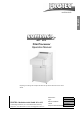
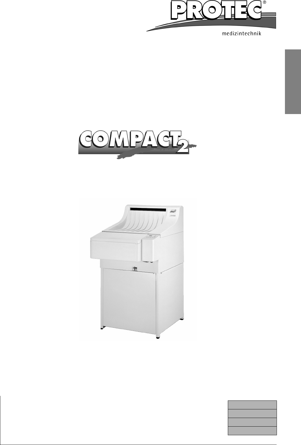
English TM SX 2 Film Processor Operation Manual Depending on model type the Compact 2 has either an open stand or like shown here a closed cabinet. Machine No.: Type: PROTEC® Medizintechnik GmbH & Co. KG Lichtenberger Straße 35, D-71720 Oberstenfeld, Germany Telephone: +49-7062-9255-0 e-mail: service@protec-med.com Date of installation: Issued: 05-2006/2.
EU-Declaration of Conformity ® EU-Declaration of Conformity PROTEC® Medizintechnik declares, that the product Description: COMPACT 2TM Machine type: X-Ray-Film Processor Model no. 117x-y-0000 x is a number between 0 and 9, y is a number between 1 and 9 conforms to the following harmonized standards: Safety: IEC 61010-1:2001 + A1:92 + A2:95; DIN 1988 T4:12/1988; UL 3101-1; CSA 22.
EU-Declaration of Conformity ® English Introduction .......................................................................................................... 3 Technical Specifications ..................................................................................... 4 Safety Instructions............................................................................................... 5 Installation .........................................................................................................
Technical Specifications ® Technical Specifications Film transport: Continuous roller transport system Film formats: Sheet and roll films up to 45.1 cm (17.7 ) width; Roll films with leader from 70 mm (2.8'') width; smallest film format 10x10 cm (4x4''). In processor type 1191 roll films in cassettes can also be processed. Cassette box (LxWxH): 53x19x16 cm (20.6x7.5x6.3'').
Technical Specifications Pollution degree: 2 System protection: IP 20 220 - 240 V~, 10 A, 50 Hz 220 - 240 V~, 14 A, 60 Hz 208 - 240 V~, 14 A, 60 Hz Unit tested to IEC 61010 (EN 61010, UL 3101, CSA 22.2-1010) overvoltage category II 2.5 kW Power consumption: Stand-by: 0.23 kWh Processing: 2.
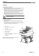
Installation ® Installation 1. Requirements for installation a. Fresh water connection: Stop cock with 3/4" outer-thread diameter (washing machine connection), Water pressure 2 - 10 bar (29 - 145 psi). b. Drainage connection: Plastic tube - inner diameter 50 mm ”or larger. A ventilated syphon which serves as odour preventor should be included in the planning. The drainage tubes should be installed with a fall of minimum 5 %. Local Water Authorities regulations should be complied with. c.
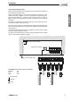
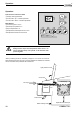
Installation ® 3. Connecting the processor Water connection: Fit water-inlet hose (grey) at the rear of the machine and connect to the prepared fresh water supply. English All other hoses (see diagram ): Connect the enclosed hoses according to colour system to backside of machine. Put hose clip (enclosed in accessory bag) over hose end, before attaching to connection. Warm up hose end (with hot water or lighter) and push onto the respective connection. Finally push clip over hose and connection.
Initial Operation ® Danger of Overflow! Use the included cable binders (accessory bag) to secure the hoses. Fix all hose ends which guide into syphon or collecting container, so that they do not drop into the liquid. Very important: The hose piping should be straight (without the hoses going up and down) with a constant fall. The hoses should be as short as possible and without bends and kinks. This is very important for the water overflow hose.
Mode of Operation ® Mode of Operation The processor develops, fixes, rinses and dries your films. The temperatures, speed and replenishment rates required for processing various types of film-materials can be individually selected and stored in the microprocessor control unit. English Automatic filling and heating When the machine is switched on, the water tank fills and chemical baths heat up automatically.
Operation ® Operation Short Overview and Control Panel c Display working parameters d Arrow button “Up” = increase parameter e Arrow button “down” = decrease parameter Mode Buttons f Processing time in minutes Select g Developer temperature in °C h Dryer temperature in °C i Replenishment developer time in seconds j Replenishment fixer time in seconds Power on Autofill Enter Memory Recall Store Exit Important! Safety function stops film transportation when cover is removed.
Operation ® Attention: English Upon first operation and each refilling of a developer check the function of the circulation pump and vent the pump if required (see page 8). Before use... 1. Close water-drainage stop cock. 2. Open water tap. 3. Switch processor on. 4. Check liquid level in replenishment and drainage collecting containers. 5. Wait until the start-cycle has been completed or until Developer temperature is reached. 6. Run cleaning films through processor. Working procedure 7.
Operation ® Switching the Machine On Before switching the machine on, open the fresh water tap and close the water drainage tap (under control panel). Then switch the machine on (main switch is situated under the control panel). Once the machine is switched on, a “Start-cycle” of eight minutes duration is activated: A replenishment cycle is carried out, the water tank fills automatically and the chemical baths heat up. During this “Start-cycle” no films can be fed into the machine.
Operation ® Time Replenishment (Antioxidation function, Flood replishment) English Also during the stand-by, the developer chemicals are subject to change which causes their deterioration. By means of the time replenishment, a replenishment cycle is activated after a set time. With this function, the quality of the developer chemicals are maintained even when standing idle for long periods. The setting-range for the time-replenishment is from 5 up to 99 minutes.
Operation ® Processing time The processing time, is the time, it takes the front end of a film from the infeed of the processor until it reaches the film exit. The processing time is set by the speed with which the film is transported through the machine. Depending on the requirements, this time can be varied from 1 to 5 minutes adjusted in 0.1-minute-steps (Adjusting the processing time: see page 13 “Setting the working parameters”).
Operation ® The chart below shows the replenishment time to be set for the requested replenisher rate per m2-film surface. The standard setting is 10 sec. with 500 ml replenisher rate per m2 film surface. The replenisher rate has to be adjusted depending on film material, chemicals and film throughput.
Operation ® Autofill Function In case new chemicals have to be filled into the processor (after installation, tank cleaning), the tanks can be filled automatically by means of the autofill function. Herewith, the tank is filled for a fixed period of 17 minutes, e.g. chemicals are pumped up from the replenisher tanks into the machine. Also the water bath will be filled (8 min. period). The display will show two symbolized tanks (see right).
Operation ® 2. Press required replenishment button for developer (7) or fixer (8) - respective button illuminates. 3. Start replenishment cycle by pressing arrow-button “up” (2) or cancel replenishment cycle by pressing arrow-button “down” (3). English Manual replenishment: 1. Switch to manual mode. In the memory five sets of parameters can be stored and be recalled into working memory. Use of Memory Function In the memory five sets of parameters can be stored and be recalled into working memory.
Operation ® Lock Function To prevent unintentional change of operation parameters the input can be locked. If the input is locked any attempt to change the parameters will display an error “LO” (locked). Activating and de-activating of the input lock: 1. Press buttons 4 and 5 “Enter Memory” simultaneously to enter the memory mode (see diagram on page 17). 2. Press several times the button 3 “Select” until the display will show “L.0”(Lock off input unlocked) or “L.1” (Lock on: input locked). 3.
Operation ® Removal and Installation of Dryer Rack (two-parts) 1. Push small, black slide (1) downwards. 2. Pull dryer plate small (2) out of the dryer. 3. The upper part of the dryer can now be removed. Hold the dryer at the front distance bar (3) and the whole of the metal plate in the back (4). 4. Take out lower part of the dryer. English Removal: Installation: 1. Insert lower dryer part. Make sure that both slides at the lower part are assembled and pushed down. 2.
Care ® Care Daily Care Before use... 1. Remove dirt and dust from film-infeed with soft cloth. 2. Run 2 - 3 cleaner films through processor to remove all accumulated dirt and dust from the rollers. 3. Check the liquid level in the replenishment containers and if necessary refill. After use... • When working has been completed at the end of the day, the water must be drained out of the machine. This reduces the growth of algae in the water bath.
Care ® Thorough Cleaning Depending on the quantity of films processed, a thorough cleaning is necessary every 3 - 6 months. Tank cleaners are available for developer and water baths. The fixer bath is cleaned with water. When preparing chemical tank cleaners, follow manufacturers instructions explicitly. 1. Switch the machine off and empty all tanks by opening the stop cocks. Attention! Machine will not drain off, if it is swichted on. 2. Remove machine cover.
Maintenance / Disposal ® Maintenance / Disposal Maintenance Protocol Installation Name: Technician: Telephone: Machine type: Training: Date: Serial number: by: Guarantee until: Developer temp.: Dev. reg. time: Developer: Changed by: Dryer temp.: Fix. reg. time: Fixer: Date: Cycle time: Anti-oxidation: Film type: Developer temp.: Dev. reg. time: Developer: Changed by: Dryer temp.: Fix. reg. time: Fixer: Date: Cycle time: Anti-oxidation: Film type: Developer temp.: Dev. reg.
Maintenance / Disposal ® Attention: Never start the machine up unless it is filled with liquid! 1. Functional check film intake / film transport / replenishment / bath heating / dryer heating / water supply 2. Cleaning 2.1. Switch off machine, remove cover 2.2. Empty all three tanks 2.3. Close drain cocks and fill tanks with water 2.4. Install cover, switch machine on 2.5.
Maintenance / Disposal ® 2.31. If required repeat items 2.20 to 2.30 (observe information concerning temperature, time, cleaning procedure contained in the 2.32. datasheet of the tank cleaning agent) 2.33. Remove roller racks from the machine and remove dirt under flowing water using a soft rag or sponge 2.34. Remove residual dirt particles in tanks and rinsing gutters. 2.35. Clean all toothed gear wheels, axles, bearings and rollers, check them for damage (replace if required) 2.36.
Problems and Solutions ® Problems and Solutions Advise on Film Defects English Your processor has been constructed for long term use. If however irregularities might occur, you will find help to locate the problem below. Please check the listed points, before calling your service-technician. Films do not have enough density • • • • • • • Bath temperature is too low. Developing time too short. Exposure time is too short. Replenishment rate of developer too low. Developer chemicals are exhausted: Renew.
Problems and Solutions ® Advice on Machine Errors Machine does not switch on • Ensure that electrical plug is firmly inserted into socket. Ensure that electrical socket has power supply by testing with an appliance e.g. tablelight. Rinsing water does not flow • Open water inflow tap. • Water pressure in the water system is too low: Pressure in the plumping system too low: Minimum pressure has to be 2 bar (29 psi).
Problems and Solutions ® • Switch machine off and remove cover. • Check in which rack the film is caught up in and remove the respective rack. • If possible, catch hold of the film end by hand and by manually turning the drive-shaft, pull the film out of the rack. • Replace the rack and secure with fastener. Replace machine cover and switch the machine on again.
Problems and Solutions ® Error messages Machine errors are shown on the display as abbreviations. The cause of error is explained below. For service technician: problem solution see “Trouble shooting” in service manual. Display Cause and possible correction E1 Cover switch is not actuated. Place cover correctly on the machine and ensure that the cover switch behind the control panel is actuated. If the error cannot be corrected, then the cover switch may be broken.
Tips and Tricks ® Tips and Tricks Removal of Control PCB To reach the screws of the control PCB remove the film over the keyboard in the front area about 20 mm (lift up). English Stop start-cycle The start-cycle (after switching the machine on) can be manually interrupted. To stop start-cycle, press both arrow-buttons (2+3) simultaneously. The start-cycle may only be interrupted for service purposes.
Tips and Tricks ® The PROMIX® A40 is a fully automatic chemical mixing machine for preparing developer and fixer bath chemicals of either powder form or liquid concentrates. All stages are guided and controlled by means of a microprocessor. Thanks to a large reserve tank, up to 3 machines can be connected and continue to operate, without having to interrupt the working process. Due to its patented construction, the PROMIX® A40 is easy to operate, reliable, fast and virtually service free.
Tips and Tricks English ® At last you can breathe again AIRCLEAN® 200 cleans the air from your processor. Unpleasant chemical odours are absorbed through the large active charcoal filter. Allergies are prevented and you can breathe again freely. Simple installation directly on to the processor (no breaking through the wall). Filter exchange cheap and fast approx. every 3 months. Ask your local dealer for more information. Technical Specifications Cleaning capacity: approx.
® 32 COMPACT 2TM
® Service Manual Table of Contents English Dimensions......................................................................................................... 34 Transport ............................................................................................................ 34 Installation Data ................................................................................................. 35 Trouble Shooting .........................................................................................
Dimensions ® Dimensions Transport To carry hold here! 34 To carry hold here! COMPACT 2TM
Installation Data ® Installation Data Working space Dimensions in cm English Wall break through for film input Through the wall monting set 1280 0 0000 Through the wall mounting film infeed - Machine in light room Existing wall break through If the machine is to be mounted to an existing wall break through of a PROTEC COMPACT 45 machine, then the wall plate order-no. 0280-0-0101 will be required.
Working space 36 Door min.
Installation Data 1 ® Mains (208) 220 - 240 V, 16 A; Cu wire-Kabel 3 x 1.5 mm2; Ground-LeakageSwitch 25 A / 30 mA; power consumption 2.2 kW. 2a Power switch 16 A; 140 cm above floor; 2b Machine connection: Socket incl. earth 60 cm above floor. English 3a Water connection: Water consumption 1.9 l/min; Water temperature may not be below 5°C; 3b Water stop cock 3/4" washing machine connection. 4 Ventilation of darkroom is necessary.
Trouble Shooting ® Trouble Shooting Summary 1 2 3 4 5 6 7 8 1 Algae ............................................................................................................ 38 1.1 Excessive algae growth in water tank.................................................... 38 General......................................................................................................... 39 2.1 Mains switch “ON” - no function............................................................. 39 2.
Trouble Shooting 2 ® General 2.1 Mains switch “ON” - no function • Ensure that electrical socket has power supply. Check machine fuses. English • Pleasse use as replacement fuses only the PROTEC®s.These fuses are optimized for use under existing conditions. • While power switch is on, check the following components: Voltage on contact of main switch - If there is no voltage, replace the respecitve component. 2.
Trouble Shooting 4 ® Baths 4.1 No circulation in developer or fixer baths • Circulation pump runs but no circulation can be registered. Air lock in heating and circulation system. To ventilate: see “1. Test run” on page 8 item b). • Particles in the pump chamber. The pump chamber can be easily opened by removing the four screws. Before opening the pump drain the bath. After cleaning re-close and ensure that the seal is correctly re-inserted and not damaged. • Pump does not run.
Trouble Shooting 5 ® Film defects 5.1 Films will not dry • Hot air comes out of air channel, but the film is still not dried to satisfaction. Check chemicals and film type. If this leads to no solution then the transport speed of the machine can be reduced (see Processing time, page 14). • English 5.2 The film does not transport correctly • Check the positioning of the roller racks and ensure that levers are closed. Check the gears on the roller racks.
Trouble Shooting ® 7.3 Dryer ventilation is too weak • If the ventilation is connected incorrectly, it runs very slowly (heating element in the air channel starts to glow). Dryer ventilation connection: X9 L black X9 Z brown X10 N blue X10 PE yellow / green 7.4 Dryer temperature cannot be reached • Check temperature sensor: Measure voltage at X24 on the power PCB between pin 3 (green) and pin 2 (brown). The value should read 0.32 V at a temperature of 32 °C.
Spare Parts English ® Pos. Order No. Description: 1 2 3 4 5 6 7 8 9 10 11 1190-0-0200 1190-0-3101 1190-0-0105 1191-0-0105 2006-0-0005 1101-0-2000 1101-0-2100 1101-0-1700 1101-0-4100 2018-0-0001 1190-0-0011 1190-0-0010 1190-0-1201 2018-0-0005 2018-0-0003 2018-0-0007 2018-0-0008 2018-0-0009 2018-0-0012 2022-0-0004 2022-0-0019 2022-0-0026 2022-0-0028 2022-0-0030 2015-0-0001 Machine cover Light protection cover Film infeed tray *Film infeed tray, graphics art Drain stop cock 10 mm Replenisher tank dev.
Spare Parts ® Installation position see page 41 32 31 33 44 30 34 37 36 38 Pos. Order No. Description: 20 21 22 23 24 2002-1-0011 2036-1-0001 0002-1-0001 0002-2-0001 0002-1-0008 0190-0-0900 Circulation pump MD-10 (circulation) Safety-transformer UL Bellows pump KB2X 230V, 50Hz Bellows pump KB2X 230V, 60Hz Valve insertion f. pos.
Spare Parts English ® Pos. Order No.
Spare Parts ® Pos. Order No. Description: 69a 70 70a 72 72a 73 74 75 0190-0-0301 1190-0-0401 0190-0-0401 1101-0-3700 1101-0-4500 1190-0-3600 1101-0-0306 1101-0-0307 Side plate dev. left w. shafts Side plate fix. right Side plate fix. left w.
Spare Parts ® Fixer (blue) English Developer (red) Water/dryer Pos. Order No.
Electric Diagrams ® Pos. Order No.
Electric Diagrams English ® COMPACT 2TM 49
Electric Diagrams Compact 2 Leistungssteuerteil ® 50 COMPACT 2TM
Clock Strobe D out OE D in Deckel DGND .. Nur mit CAD andern frei. Fs/TK Name GND 14 gepr. 09.09.05 D4-PB 28 VCC b9_PE E3 + And.- Nr. D3-PB .. C60 E5 Datum GND 10 20 VCC +5V nc23 C45 C29 nc22 13 9 10 6 4 2 nc21 D5-F D5-D nc20 D5-E D5-C D5-B D5-A V16 V18 nc19 12 8 11 5 3 1 nc12 nc13 Name D1-PB nc10 nc15 .. D5-PB nc16 .. nc17 GND 7 14 VCC nc18 3 R44 C54 D2-PB Name ..
C14 C3 1 2 3 4 Bath Nur mit CAD andern frei. Fs/TK gepr. 09.09.05 .. C11 Name 1 2 Js/TD b9_PE X27 Fusschalter b9_PE C1 1 2 3 4 C2 Trockner Dryer X24 b9_PE Bad X25 Datum gez. 09.09.05 E D C B A And.- Nr. .. C4 R23 R1 Datum R4 R6 C21 C7 b9_PE C13 C20 U_ref + b9_PE L1 +5V R19 R24 Name C33 R22 R5 R33 R28 3 2 C39 5 6 C22 .. + - + - .. N2-B R17 N2-A R18 7 1 gepruft And.- Nr Datum . R58 PE7 R16 R9 Name C41 V4 +5V ..
2 3 N PE 2 3 N PE 3 PE Nur mit CAD andern frei. Fs/TK gepr. 09.09.05 .. 3 PE Name 2 N L 1 3 X1 2 N PE L 1 3 PE X14 2 L N 1 2 X2 1 L N X5 1 L X3 1 L Js/TD TRAFO Transformer prim. 230V Frei fuer Erweiterung NETZ Power Zusatzluefter Fan Umwaelzpumpe E circulation pump DEV Umwaelzpumpe F circulation pump FIX Datum gez. 09.09.05 E D C B A X4 And.- Nr. ..
Electric Diagrams ® Important: For machine type COMPACT 2 Jumper no. X7 should be placed in pos. 2-3.
Electric Diagrams English ® COMPACT 2TM 55
Electric Diagrams 56 ® COMPACT 2TM
COMPACT 2 NDT ® Order No. 1193 - X - Y000 X: 1 50 Hz 2 60 Hz Y: 0 Open working table 7 Closed base The Film Processor Compact 2 series was extended by a further version. Introduction English Processing time and developer temperature of the Compact 2 NDT processor have been adjusted to the requirements of NDT-films. This results in the following modifications compared with the Compact 2 standard processor.
COMPACT 2 NDT ® Spare parts list (compare pages 40 to 44) Pos. Order No.