
Photo Printer User Manual


COMPACT 2
TM
37
Installation Data
English
®
1 Mains (208) 220 - 240 V, 16 A; Cu wire-Kabel 3 x 1.5 mm
2
; Ground-Leakage-
Switch 25 A / 30 mA; power consumption 2.2 kW.
2a Power switch 16 A; 140 cm above floor;
2b Machine connection: Socket incl. earth 60 cm above floor.
3a Water connection: Water consumption 1.9 l/min; Water temperature may not
be below 5°C;
3b Water stop cock 3/4" washing machine connection.
4 Ventilation of darkroom is necessary.
5 Drainage hose, diameter 50 mm, acid resistant; odour preventor with connec-
tion for 10 mm hose.
6 Drainage for Developer; connection for 10 mm hose. Respective collecting
containers have to be supplied. Local water board regulations have to be
complied with!
7 Drainage for Fixer; connection for 10 mm hose. Respective collecting contain-
ers have to be supplied. Local water board regulations have to be complied
with!
8 Sink with hot/cold water and flexible hose; Inner dimensions are 60x40x30 cm
deep; Material: ceramics, stainless steel, plastics.
9 The replenishment containers can be placed under the processor or can be
installed externally.
10 Wall break through for film exit through the wall infeed (page 35): Processor is
installed outside the darkroom, the film exits into the light-room. For the alter-
ation “Through the wall mounting infeed” the assembly kit no. 1280-0-0000 is
necessary..
11 Wall break through for film exit through the wall output (page 36): Processor is
installed inside the darkroom, the film exits through the wall to the light-room.
For the alteration “Through the wall mounting film output” the assembly kit no.
1281-0-0000 is necessary.
Film exit through the wall
On machines which have the film exit through the wall into the light room, the fol-
lowing modifications have to be made:
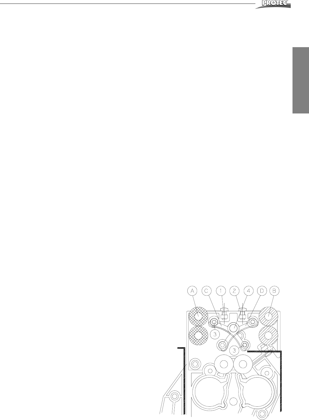
Dryer rack
Remove the two rollers from pos. A. To do this open bolt from
spring at pos. 1 and remove gear from lower roller.
Move curved guide bar from pos. C to D. To do this open bolt 3
and 4.
Install the two rollers in pos. B. Mount spring at pos. 2.
Machine cover
The front film exit opening in the machine cover has to be closed
with the screen contained in the assembly kit.
For the alteration “Through the wall mounting film output” the
assembly kit no. 1281-0-0000 page 48 is necessary.