
Indoor Furnishings User Manual


Page 3
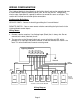
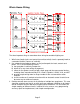
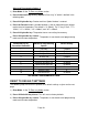
WIRING CONFIGURATION
The Lighting Module is wired directly to the lighting circuit and can be controlled by one
or more Remote switches producing three, four, or five-way circuits. Multiple-way
circuits make it possible for a group of switches to control the same set of lights. This
section will illustrate how to hook-up the connections.
Configuration Definitions:
SERVICE PANEL - Source of electricity providing the Line and Neutral
REMOTE SWITCH - One or more remote switches controlling the light circuit via the
Lighting Module control inputs.
Wiring Notes:
a. Remote switches require a Line Voltage input (Black) that is always hot. Do not
connect to the load (switched) circuit.
b. The gray wire on the Remote Switch only serves to light the red LED, which
provides as a night light and power indicator. It does not indicate the state of t he
load. This wire can be tied to neutral or earth ground.
Wiring Diagram
Ground
CNTRL1
LOAD1
CNTRL2
LOAD2
CNTRL3
LOAD3
CNTRL4
LOAD4
WHITE
LINE
Light
Fixture 1
Light
Fixture 2
Light
Fixture 3
Light
Fixture 4
Line
Neutral
Gnd* Gnd* Gnd* Gnd*
Remote 1 Remote 2 Remote 3 Remote 4
Lighting Module
(Gray)
(Yellow)
(Black)
Remote
Switches
(Optional)
* Can be connected to Nuetral