
User`s manual


Appendix B Technical Summary
Page: B-8
Prox-1750G1/G2 USER
′
S MANUAL
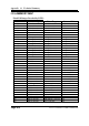
Memory Decode Ranges From Processor Perspective :
Memory Range Target Dependency/Comments
0000 0000h-000D FFFFh
0010 0000-TOM (Top of
Memory)
Main Memory TOM registers in Host Controller
000E 0000h-000F FFFFh FWH Bit 7 in FWH Decode Enable
Register is set
FEC0 0000h-FEC0 0100h I/O APIC inside ICH2
FFC0 0000h-FFC7 FFFFh
FF80 0000h-FF87 FFFFh
FWH Bit 0 in FWH Decode Enable
Register
FFC8 0000h-FFCF FFFFh
FF88 0000h-FF8F FFFFh
FWH Bit 1 in FWH Decode Enable
Register
FFD0 0000h-FFD7 FFFFh
FF90 0000h-FF97 FFFFh
FWH Bit 2 in FWH Decode Enable
Register is set
FFD8 0000h-FFDF FFFFh
FF98 0000h-FF9F FFFFh
FWH Bit 3 in FWH Decode Enable
Register is set
FFE0 0000h-FFE7 FFFFh
FFA0 0000h-FFA7 FFFFh
FWH Bit 4 in FWH Decode Enable
Register is set
FFE8 0000h-FFEF FFFFh
FFA8 0000h-FFAF FFFFh
FWH Bit 5 in FWH Decode Enable
Register is set
FFF0 0000h-FFF7 FFFFh
FFB0 0000h-FFB7 FFFFh
FWH Bit 6 in FWH Decode Enable
Register is set
FFF8 0000h-FFFF FFFFh
FFB8 0000h-FFBF FFFFh
FWH Always Enabled.
The top two 64K blocks of this
range can be swapped as
described in Section 6.4.1.
FF70 0000h-FF7F FFFFh
FF30 0000h-FF3F FFFFh
FWH Bit 3 in FWH Decode Enable 2
Register is set
FF60 0000h-FF6F FFFFh
FF20 0000h-FF2F FFFFh
FWH Bit 2 in FWH Decode Enable 2
Register is set
FF50 0000h-FF5F FFFFh
FF10 0000h-FF1F FFFFh
FWH Bit 1 in FWH Decode Enable 2
Register is set
FF40 0000h-FF4F FFFFh
FF00 0000h-FF0F FFFFh
FWH Bit 0 in FWH Decode Enable 2
Register is set
Anywhere in 4GB range D110 LAN Controller Enable via BAR in Device
29:Function 0 (D110 LAN
Controller)
All Other PCI None