
Technical information


Page 10
Com-Tech Power Amplifiers
Reference Manual
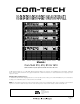
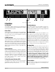
2 Facilities
A. Filter Grille
A metal grille supports and protects the dust filter (B).
To clean the dust filter, detach the grille by removing the
screws that fasten it in place.
B. Dust Filter
The dust filter removes large particles from air drawn by
the cooling fan. (The fan is an option for 120 VAC, 60 Hz
Com-Tech 210s.) Clean the filter regularly to prevent
clogging (see Section 4.5).
C. ODEP
Indicators
Each channel has an amber front panel indicator that
shows thermal-dynamic energy reserve. Normally, each
ODEP indicator is lit to show available reserve energy.
The indicator will dim proportionally as the energy re-
serve for its channel decreases. In the rare event that a
channel has no reserve, its indicator will turn off and the
ODEP circuitry will limit the channel’s output drive (see
Section 4.2).
D. IOC
Indicators
The yellow IOC (Input/Output Comparator) indicators
serve as sensitive distortion indicators to provide
proof
of distortion-free performance
. Under normal condi-
tions, the indicators remain off. They light up if the out-
put waveform differs from the input by 0.05% or more.
In addition, when the amplifier is running in parallel/
mono mode, CH2 IOC stays on under normal condi-
tions (see Section 4.2).
E. Signal Presence Indicators (SPI)
The signal presence indicators flash synchronously with
the amplifier’s audio output, when the output voltage is
greater than 34 mV. (see Section 4.2).
F. Enable Indicator
This indicator lights when the amplifier has been en-
abled, or turned on, and AC power is available. The
enable indicator will dim when the energy saving circuit
is activated (see Section 4.2).
G. Enable Switch
This rocker switch is used to turn the amplifier on, off,
and enable the remote feature. When turned on by ei-
ther the rocker switch or the remote R.S.V.P. module, the
output is muted for about four seconds to protect your
system from any turn-on transients. Delay times vary
slightly from one unit to the next, so there is always a
certain amount of “randomness”. Turn-on inrush is lim-
ited by Soft-Start circuitry, so Com-Tech amplifiers never
need a power sequencer. (To change the turn-on delay
time, contact Crown’s Technical Support Group.)
H. Power Cord
All 120 VAC, 60 Hz North American units have a
NEMA 5-15P plug with an integral voltage presence
lamp. These units include a 16-gauge power cord with
each Com-Tech 210 and 410, and a 14-gauge cord with
each Com-Tech 810 and 1610. Other units have an ap-
propriate power cord and plug. All Com-Tech “10” Se-
ries amps utilize a convenient 3-foot-long power cord.
To meet full regulatory compliance, these cords
must be plugged into a local, cabinet mounted, com-
mercial grade electrical outlet box. “Extension”
cords are not recommended or adequate.
Refer to
Section 7 for more information on power usage.
I. Reset Switch
This reset switch is used to reset the circuit breaker that
protects the power supplies from overload (see Sec-
tions 4.3.4 and 4.4).
Fig. 2.1 Front Facilities