
Technical information


Page 12
Com-Tech Power Amplifiers
Reference Manual
3 Installation
This section covers basic Com-Tech installation proce-
dures. All Com-Tech
amplifiers are intended for rack
mount installations using a commercial 19-inch
(48.3-cm) EIA rack standard metal cabinet wired with
a commercial grade electrical outlet box and recep-
tacles. All Com-Tech Amplifiers utilize a convenient
3-foot long (0.9-m) power cord for such installations.
3.1 Mounting
Com-Tech amplifiers are designed for standard 19-inch
(48.3-cm) rack mounting or stacking without a cabinet.
In a rack, it is best to mount units directly on top of each
other. This provides the most efficient air flow and sup-
port. If the rack will be transported, we recommend that
you fasten the amplifier’s back panel securely to the
rack to help support the unit’s weight.
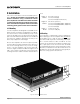
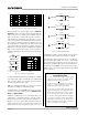
All Com-Tech amplifiers are 19 inches (48.3 cm) wide,
16 inches (40.6 cm) deep, and 0.25 inches (0.6 cm) in
front of the mounting surface. As you can see in Fig-
ure 3.1, Com-Tech amplifiers vary in their vertical di-
mensions. Figure 3.1 labels the different heights as A, B
and C. These letters correspond to the list that follows
showing
Com-Tech
models and their vertical dimen-
sions.
Height A: 3.5 inches (8.9 cm)
Models: Com-Tech 210 (All)
Com-Tech 410 (North American)
Height B: 5.25 inches (13.3 cm)
Models: Com-Tech 410 (100/120 VAC, 50/60 Hz)
Com-Tech 410 (220/240 VAC, 50/60 Hz)
Com-Tech 810 (All)
Height C: 7 inches (17.8 cm)
Model: Com-Tech 1610 (All)
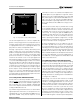
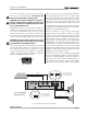
3.2 Cooling
It is important to understand cooling considerations
when installing a Com-Tech amplifier. First, never block
the amplifier’s front or side air vents. This can cause
poor air flow and may result in overheating. If the ampli-
fier is rack-mounted, its sides should be at least
2 inches (5 cm) away from the cabinet (see Figure 3.2).
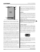
Also, open spaces in the front of the rack should be
covered with blank panels to prevent improper air flow.
Otherwise, heated air from the side exhaust vents can
be drawn into the front air intake which may greatly re-
duce the cooling system’s effectiveness.
Fig. 3.1 Mounting Dimensions