
Technical information


Page 28
Com-Tech Power Amplifiers
Reference Manual
Again, this should only be possible when operating
out-
side rated conditions
, as when the amplifier is used to
drive a 1-ohm load, or when an input signal is clipped
severely.
4.4 Controls
The Enable switch is located on the front panel so you
can easily turn the amplifier on and off. If you ever need
to make any wiring or installation changes, don’t forget
to disconnect the power cord. Please follow these steps
when first turning on your amplifier:
1. Turn down the level of your audio source. For
example, set your mixer’s volume to “∞.”
2. Turn down the level controls of the amplifier.
3. Turn on the Enable switch. The Enable indicator
should glow. During the four second turn-on delay
which immediately follows, the indicators will flash
as described in Figure 4.1. After the delay, the
ODEP indicators should come on with full bril-
liance and the IOC and Signal Presence Indica-
tors should function normally.
4. After the turn-on delay, turn up the level of your
audio source to the desired level.
5. Turn up the Input Attenuation controls on the back
panel of the amplifier until the desired loudness or
power level is achieved.
6. Turn down the level of your audio source to its
normal range.
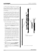
A 21-position detented Input Attenuation control is
provided for each channel. For security, the level con-
trols are located on the back panel. To discourage tam-
pering from the rear, a Lexan cover is provided that can
be attached to the back panel with the included ½-inch
8-32 screws.
Com-Tech
amplifiers have a reset switch for the AC
circuit breaker. If the circuit breaker trips, the Enable
indicator turns off. In this situation, turn off the Enable
switch and reset the circuit breaker. Then, turn the En-
able switch back on. If it trips again or the unit fails to
operate properly, contact an authorized service center
or Crown’s Technical Support Group.
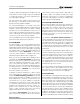
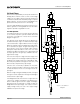
A three-position input sensitivity switch is located in-
side the amplifier’s PIP compartment. It is set at the fac-
tory to a sensitivity of 0.775-volts (8/4-ohm mode).
Fig. 4.3 Input Sensitivity Switch
Please notice that there is a separate 0.775-volt position
for 70-volt mode. If desired, the sensitivity can be
switched to a voltage gain of 26-dB. With 26-dB gain
and 70-volt output, the input sensitivity for all models is
3.5 volts. With 26-dB gain and 8/4-ohm output, the in-
put sensitivity varies among the different amplifier mod-
els. To generate rated 1-kHz power, the input voltage
required is 1.48 volts for the Com-Tech 210, 2.12 volts
for the Com-Tech 410, 2.47 volts for the Com-Tech 810,
and 3.29 volts for the Com-Tech 1610.
It is also possible to configure the amplifier with one
channel set to 8/4-ohm output and the other set to 70-
volt. With this configuration, the input sensitivity switch
should be set to 0.775 volts (70 volt), and the Input At-
tenuation control for the 8/4 ohm channel can be ad-
justed to compensate for the additional gain.
To change the input sensitivity:
1. Turn off the amplifier and disconnect the power
cord from the receptacle.
2. Remove the PIP module.
3. Locate the access hole for the Input Sensitivity
switch inside the chassis opening (Figure 4.3).
Note: The input sensitivity switch is not visible
because it is mounted below the hole. Use your
little finger to reach it.
4. Set the switch to the desired position noted on the
access hole label.
5. Replace the PIP module and restore power.
0.77 V
sensitivity
8/4 ohm
26 dB
gain
SENSITIVITY SWITCH INSIDE ACCESS HOLE
0.77 V
sensitivity
70 volt
FIRST GENERATION P.I.P. MODULES REQUIRE THE
PIP2 ADAPTER
FOR CONNECTION. PLEASE REFER TO REFERENCE MANUAL.
CH-2 CH-1INPUT ATTENUATION
∞
50
30
24
21
18
16
14
12
11
9
8
7
6
5
4
3
2
1
.5
0
dB
∞
50
30
24
21
18
16
14
12
11
9
8
7
6
5
4
3
2
1
.5
0
dB