
Technical information


Page 29
Com-Tech Power Amplifiers
Reference Manual
5 Technical Information
5.1 Overview
Com-Tech amplifiers incorporate several new techno-
logical advancements including real-time computer
simulation, low-stress output stages, an advanced heat
sink embodiment and the Programmable Input Proces-
sor (PIP) expansion system.
Custom circuitry is incorporated to limit temperature and
current to safe levels, making it highly reliable and toler-
ant of faults. Unlike many lesser amplifiers, it can oper-
ate at its voltage and current limits without
self-destructing.
Real-time computer simulation is used to create an ana-
log of the junction temperature of the output transistors
(hereafter referred to as the output devices). The
amplifier’s output is limited only when the device tem-
perature becomes excessive (and by the minimum
amount required). This patented approach called Out-
put Device Emulation Protection (or ODEP) maximizes
the available output power and protects against over-
heating—the major cause of device failure.
The amplifier is protected from all common hazards that
plague high-power amplifiers, including shorted, open
or mismatched loads; overloaded power supplies; ex-
cessive temperature and chain-destruction phenom-
enon; input overload; high-frequency blowups, internal
faults; and input and output DC.
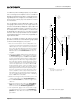
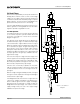
The four-quadrant topology used in a Com-Tech
amplifier’s output stages is called the
Grounded Bridge
.
This patented topology makes full use of the power sup-
ply, providing peak-to-peak voltages to the load that are
twice the voltage seen by the output devices (see Fig-
ure 5.1).
As its name suggests, the
Grounded Bridge
topology
is referenced to ground. Composite devices are con-
structed to function as large NPN and PNP devices to
handle currents which exceed the limits of available
devices. Each output stage has two composite NPN
devices and two composite PNP devices.
The devices connected to the load are referred to as
“high-side NPN and PNP” and the devices connected
to ground are referred to as “low-side NPN and PNP.”
Positive current is delivered to the load by increasing
conductance simultaneously in the high-side NPN and
low-side PNP stage, while synchronously decreasing
conductance of the high-side PNP and low-side NPN.
The two channels may be used together to double the
voltage (Bridge-Mono) or current (Parallel-Mono) pre-
sented to the load. This feature gives you flexibility to
maximize power available to the load.
A wide bandwidth, multiloop design is used for state-
of-the-art compensation. This produces ideal behavior
and results in ultra-low distortion values.
Aluminum extrusions have been widely used for heat
sinks in power amplifiers due to their low cost and rea-
sonable performance. However, measured on a watts-
per-pound or watts-per-volume basis, the extrusion
technology doesn’t perform nearly as well as the heat
exchangers developed for Com-Tech amplifiers.
Our heat exchangers are fabricated from custom con-
voluted fin stock that provides an extremely high ratio of
area to volume, and area to weight. All power devices are
mounted directly to massive heat spreaders that are elec-
trically at the Vcc potential. Electrifying the heat spread-
ers improves thermal performance by eliminating an
insulating interface underneath each power device. The
chassis itself is used as part of the thermal circuit to
maximize utilization of the available cooling resources.
4.5 Energy Saving Circuit Application
The new CT-10 Series amplifiers incorporate a new
feature to significantly decrease the use of energy
when the amplifier is idle. The Energy Saving circuit
allows the amplifier to cut back its energy consumption
based on the signal level offered to the inputs. Over
time, this circuitry provides the end user better value by
saving on air conditioning requirements and utility
expenses.
This circuit is normally active at all times. Whenever
both input signals drop below an absolute 5 mV at the
output connector for 30 minutes, the Energy Saving
circuit cuts back the amplifier power consumption. As
either input signal returns and the output signal rises
past the 5 mV threshold, the amplifier power
consumption returns to its operating levels.
4.6 Filter Cleaning
A dust filter is provided on the amplifier’s air intake (Fig-
ure 2.1). If this filter becomes clogged, the unit will not
cool as efficiently as it should and high heat sink tem-
peratures may produce lower-than-normal output.
Dust filters are not 100% efficient—depending on the
local environment, the internal heat sinks of the amplifier
will benefit from periodic cleaning by a qualified techni-
cian. Internal cleaning information is available from our
Technical Support Group.