
Technical information


Page 7
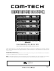
Com-Tech Power Amplifiers
Reference Manual
ILLUSTRATIONS
1.1
Com-Tech
Amplifiers (120 VAC, 60 Hz Units) ............................. 8
2.1 Front Facilities ......................................................................... 10
2.2 Rear Facilities ......................................................................... 11
3.1 Mounting Dimensions .............................................................. 12
3.2 Top View of a Rack-Mounted Unit ............................................ 13
3.3 Extra Cooling with a Rack-Mounted Blower ............................. 14
3.4 Wiring for Dual 8/4 Ohm Mode ................................................ 15
3.5 Wiring for Dual 70 Volt Mode ................................................... 16
3.6 Wiring for Bridge-Mono 70 Volt Mode (140 Volt Output) ........... 17
3.7 Wiring for Parallel-Mono 70 Volt, Bridge-Mono 8/4 Ohm
and Parallel-Mono 8/4 Ohm Modes ......................................... 18
3.8 Balanced Input Wiring ............................................................. 19
3.9 Unbalanced Input Wiring......................................................... 19
3.10 Infrasonic Filter Capacitor Values ............................................ 20
3.11 Unbalanced RFI Filters ............................................................ 20
3.12 Balanced RFI Filters ................................................................ 20
3.13 Connecting the RSVP Module ................................................. 21
3.14 Wire Size Nomograph ............................................................. 22
3.15 Inductive Load (Transformer) Network ..................................... 23
3.16 Loudspeaker Fuse Nomograph ............................................... 24
4.1 Indicators ................................................................................ 25
4.2
ODEP
,
IOC
and Signal Presence Indicator States .................... 26
4.3 Input Sensitivity Switch ............................................................ 28
5.1 Circuit Block Diagram ............................................................. 30
6.1
Com-Tech 210
Minimum Power Matrix ..................................... 35
6.2
Com-Tech 410
Minimum Power Matrix ..................................... 36
6.3
Com-Tech 810
Minimum Power Matrix ..................................... 37
6.4
Com-Tech 1610
Minimum Power Matrix ................................... 38
6.5
Com-Tech 210
Maximum Power Matrix .................................... 39
6.6
Com-Tech 410
Maximum Power Matrix .................................... 40
6.7
Com-Tech 810
Maximum Power Matrix .................................... 41
6.8
Com-Tech 1610
Maximum Power Matrix .................................. 42
6.9 Typical Frequency Response .................................................. 43
6.10 Typical Damping Factor .......................................................... 43
6.11 Typical Output Impedance ...................................................... 43
6.12 Typical Phase Response ......................................................... 44
6.13 Typical Crosstalk ..................................................................... 44
7.1
Com-Tech 210
Power Draw, Current Draw and
Thermal Dissipation at Various Duty Cycles ............................. 45
7.2
Com-Tech 410
Power Draw, Current Draw and
Thermal Dissipation at Various Duty Cycles ............................. 46
7.3
Com-Tech 810
Power Draw, Current Draw and
Thermal Dissipation at Various Duty Cycles ............................. 46
7.4
Com-Tech 1610
Power Draw, Current Draw and
Thermal Dissipation at Various Duty Cycles ............................. 46
8.1
PIP2
Adaptor Connection ........................................................ 47
8.2 Installing a
PIP
Module ............................................................ 47