
Operating instructions


Menu List
113
Chapter 6 Menu and Detailed Settings
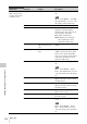
VF Setting
Makes settings related
to the viewfinder
screen.
Color –99 to ±0 to +99 Adjusts the density of the colors
displayed in the viewfinder screen.
Mode Color/B&W Selects “Color” or “B&W” as the
display mode of the viewfinder
screen. (Even when “B&W” is
selected, some indications are
always displayed in color. Examples
include tally indications,
thumbnails, and the skin gate area.)
Peaking Type Normal/Color/Both Selects the peaking type.
Normal: Normal peaking
Color: Color peaking
Both: Both
Peaking Frequency Normal/High Selects “Normal” or “High” as the
peaking frequency.
Peaking Color White/Red/Yellow/Blue When “Peaking Type” is set to
“Color,” selects the peaking color
from among “White,” “Red,”
“Yellow,” and “Blue.”
Peaking Level Low/Mid/High When “Peaking Type” is set to
“Both,” selects the color peaking
level from among “Low,” “Mid,” and
“High.”
DXF Rec Tally Upper/Both When a separately sold viewfinder is
installed, specified whether to light
the tally indicator on the upper side
only (“Upper”), or on both the upper
and lower sides (“Both”).
Marker
Makes settings related
to marker display in the
viewfinder screen.
Setting On/Off Turns all markers on or off.
Note
When Marker is assigned to the
ASSIGN. 2 switch, this setting is
disabled.
Center Marker 1/2/3/4/Off When the center marker is
displayed, selects the type. Select
“Off” if you do not want to display
the marker.
Note
When “Safety Zone,” “User Box,”
and “Guide Frame” are set to “On,”
this setting cannot be turned on.
Center H Position –40 to 0 to 40 Specifies the horizontal position of
the center marker.
Center V Position –40 to 0 to 40 Specifies the vertical position of the
center marker.
OPERATION
Menu items Sub-item Settings Description