GE Security Simon XT V2 User Manual P/N 466-2266-01 • REV A • ISS 24FEB10
Copyright © 2010 GE Security, Inc. This document may not be copied in whole or in part or otherwise reproduced without prior written consent from GE Security, Inc., except where specifically permitted under US and international copyright law. Disclaimer The information in this document is subject to change without notice. GE Security, Inc.
Content Introduction 3 Using the Simon XT security system 5 Panel controls 5 Simon XT features 7 Home security 8 Exit/entry delay 9 Bypassing sensors 11 Alarms 11 Chimes 12 Latchkey 13 System status 13 Using an offsite phone 14 Touchpads and key fobs 14 How your system communicates 16 Status beeps 16 Alarm sirens 17 Panel indicator lights 17 Trouble beeps 18 Programming 20 System menu 20 Code options 20 Menu navigation 21 Set clock 22 Chime 22 Special chime 23 System tests 24 Revision 24 Contrast 24 System
Emergency planning 34 Sensor and module locations 35 Access codes 36 Delays 37 Simon XT system quick reference 37 ii Simon XT V2 User Manual
Introduction The Simon XT uses wireless technology to warn your family about intrusion, carbon monoxide and fire. The system communicates with a central monitoring station and sends voice messages to an offsite phone. The security system uses sensors that communicate alarms to the control panel using radio waves. The system is supervised, meaning that the panel checks the status of each sensor to detect problems.
Component Type Description Personal help button A wireless device used for activating police, fire, or auxiliary alarms through your security system. You can send commands or instruct your security system through a series of key presses on the panel, touchpads, or a remote telephone. Table 2: System communication devices Device Description Control panel You can enter commands for your security system through simple key presses on the panel.
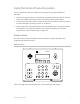
Using the Simon XT security system You can operate the self-contained security system through several different methods: • Use the front panel buttons to arm/disarm the system when you enter or exit your home and to determine which sensors are active and the system status. • Use the three fast action keys to communicate with the central monitoring station to report emergency (auxiliary), police, or fire alarms.
Table 3: Panel keys and features Control Description Piezo siren Provides alarm beeps and status beeps. LCD display Provides a 2 x 16 character array that displays a variety of phrases and icons. Scroll up/scroll down arrows Press to scroll through lists of similar items. OK Press to select a particular menu item or commit to panel memory a menu item that has just been programmed. Doors+Windows Press to arm perimeter sensors. Motions Press to arm interior sensors.
• • Motions Doors+Windows and Motions The phrase “no delay” is appended to the arming level when no entry delay is active. Possible status icons include: • • • Chime (solid bell) Special chime (outlined bell) Latchkey on (key) LEDs Every key on the front keypad has an LED behind it, except for the scroll arrow keys. There are four status LEDs behind the row of keys below the LCD display. These status LEDs indicate the arming level. There is one status LED behind the OK button.
Home security The Simon XT allows you to control which sensors are active at any given time. Table 4 below describes the arming levels that you can set from the control panel. Table 4: Arming levels Level Function Description 0 Subdisarm If your system includes 24-hour protection sensors, you must subdisarm the panel before accessing these areas to avoid causing an alarm. Environmental sensors (such as smoke or carbon monoxide detectors detectors) stay active at all times.
To arm doors and windows (level 2): 1. Ensure that all doors and windows are closed. 2. Press Doors+Windows. 3. Enter your code when the display shows Enter Code, if a code is required. The panel displays Doors + Windows, speaks Doors and Windows On, and the Doors+Windows button lights up. The panel starts an exit delay and sounds exit beeps in groups of two until the exit delay expires. To arm motion sensors (level 3): 1. Press Motions. 2.
Function Description No delay If the system was armed with the no delay feature activated, there will be no entry delay and the alarm will occur immediately. Exit delay The exit delay is the amount of time the system gives you to exit the home before the system is armed. During the delay, you can vacate the premises through a delayed response door without causing an alarm. Beeps will sound during the exit delay (see “Status beeps” on page 16). The exit delay time is programmed by the installer.
Note: The designated door may be opened and closed only once. If you close the designated door behind you when you exit, you will need to disarm the system upon reentering. Leave the designated door open while using the quick exit feature. Exit delay extension If enabled by your installer, the exit delay extension feature will recognize when you arm the system, leave your house and then quickly reenter (for example, if you forget your car keys).
Canceling and preventing accidental alarms One of the biggest concerns you might have regarding your security system is causing an accidental alarm. Most accidental alarms occur when leaving the residence after arming the system or before disarming the system upon your return. There is a communicator delay (dialer delay) of 30 seconds programmed into the panel. The panel will delay 30 seconds before dialing the central monitoring station remote phone to send reports.
Voice chime Your installer may have programmed the system to speak the sensor name or make a custom chime sound when a chime sensor is tripped. The chime sound, if programmed, will be played in place of the standard chime beeps. Special chime The special chime feature allows you to install motion sensors in a patio or at the front door, and be notified when someone is approaching those areas. These motion sensors are not used for intrusion protection.
Using an offsite phone If enabled by the installer, you can control your Simon XT panel remotely from an offsite phone. The panel answers a phone call according to the dialing method programmed by your installer. After a certain combination of rings and pauses, the panel will answer the call with the voice prompt Enter Your Code. You must enter the correct code to gain access.
Caution: To avoid causing false alarms, check with your installer on how your touchpad/key fob options are programmed. Panic alarms need to be silenced from the panel, a remote touchpad, or another key fob. They cannot be silenced from the same key fob that activated the alarm. For any key press on the key fob, hold the button until the indicator light blinks.
How your system communicates Your system communicates by using status beeps, alarm sirens, panel indicator lights, and trouble beeps. Status beeps The panel sounds status beeps to alert you to various system events and conditions. Note: You may receive a different number of status beeps if you press the buttons quickly. Table 8: Status beeps Activity Beep response Doors+Windows Exit delay and entry delay beeps sound two times every 5 seconds and two times per second during the last 10 seconds.
Alarm sirens Exterior and interior sirens make three different alarm sounds on the premises, each indicating a different type of alarm. Sirens are programmed by the installer to time out and stop sounding after a specified time. Table 9: Siren sounds Function Fire Intrusion Emergency Interior and panel siren Temporal 3 Steady Fast on/off Exterior siren Temporal 3 Steady Note: Temporal 3 refers to a continuous pattern of three siren pulses, then off for 1.
Trouble beeps Your security system is able to automatically test itself for: • • • • Power failures Low batteries Nonworking sensors Communication trouble with the central monitoring station When your system detects one of the problems above, six rapid beeps sound every minute until the trouble condition is corrected. To stop the trouble beeps, press Status or arm then disarm the system while the trouble condition exists. Trouble beeps will resume 4 hours later unless the trouble condition is corrected.
Condition Description Failure to communicate This condition occurs if your security system cannot communicate to the central monitoring station. Your system will try to report to the central monitoring station eight times before it tells you there is a failto-communicate problem. Trouble beeps will start and the Status button will light. Press the Status button and the display will show “Comm Test Fail or Comm Failure”. You may need to call your security system dealer if the problem continues.
Programming Your Simon XT security system allows you to program certain user options. These options are accessed through a system menu. System menu To enter the system menu, press one of the scroll buttons or the OK button in the upper right of the panel. Press Status to exit a menu or option edit mode and navigate up one level. Pressing Status while in the top menu level exits the system menu.
Menu navigation Each menu contains a list of options and/or submenus. Press the scroll buttons to navigate the list of options and submenus in that menu. Pressing OK after navigating to an option selects that option for editing and flashes the current value. Pressing OK after navigating to a submenu enters that submenu, making a new list of options accessible. Pressing Status exits a menu and goes to the next higher level.
Set clock If the panel loses both AC and battery power, then upon restoring power the system time will default to midnight and blink, indicating it has not been set correctly. Your installer can set your system time to display in either 12-hour or 24-hour format. Time of day format is HH:MMx, where: HH = 01 to 12 (12-hour format) or 00 to 23 (24-hour format) MM = 00 to 59 X = a or p (12-hour format) or none (24-hour format) To reset the clock: 1. Scroll until the display shows Set Clock, and then press OK.
2. Enter your code with the numeric keys, and then press OK. The display shows the date. 3. Press OK. The display flashes the year. 4. Scroll to set the year, and then press OK to accept the setting. The display flashes the month. 5. Scroll to set the month, and then press OK to accept the setting. The display flashes the day. 6. Scroll to set the day, and then press OK to accept the setting. The display shows the programmed date. 7. Press Status twice to exit.
Note: This menu option will not appear if special chime sensors are not in your system. System tests This menu lets you run sensor and communication tests, and initiate a phone call from the panel to Enterprise Downloader. For more information, see “Testing” on page 30. Revision This menu is a read-only display of the system’s firmware version. Press Status to exit. Contrast To adjust the contrast of the display: 1. Scroll until the display shows Contrast, and then press OK. 2.
The sections below describe the options that you can program in the System Programming menu. Access codes There are three types of access codes: Master code. The master code is your most powerful code and can be used for all user operations including programming. The initial value of the master code is 123, 1234, 12345, or 123456, depending on the installer-programmed access code length. User codes 1 to 8.
3. Scroll until the display shows Duress Code, and then press OK. The current value of the code flashes. 4. Enter a new code (use the correct length), and then press OK. 5. Press Status repeatedly to exit. Security The Security menu contains the download enable option. This option determines whether your dealer can access the system remotely. To program the download enable option: 1. Enter the System Programming menu. 2. Scroll until the display shows Security, and then press OK. 3.
Timers The latchkey time option is the only timer setting available to you. The latchkey time is the time of day by which the panel must be disarmed to avoid triggering a latchkey alarm, if the latchkey time option is enabled during arming. To change the latchkey time: 1. Enter the System Programming menu. 2. Scroll until the display shows Timers, and then press OK. 3. Scroll until the display shows Latchkey Time, and then press OK. The HH (hours) part of the time flashes. 4.
Panel voice. (Spoken phrases on the speaker and key press sounds from the speaker heard while the controlling the system.) This option determines whether the panel speaks status messages and arming level changes. To program panel voice: 1. Enter the System Programming menu. 2. Scroll until the display shows Siren Options, and then press OK. 3. Scroll until the display shows Panel Voice, and then press OK. The current value of this option flashes (On or Off). 4.
Speaker volume. This option sets the volume of the panel speaker for key presses and alarm sounds. The numerical range is 1 to 8. The default value is 8. To program status beep volume: 1. Enter the System Programming menu. 2. Scroll until the display shows Siren Options, and then press OK. 3. Scroll until the display shows Speaker Volume, and then press OK. The current value of this option flashes (1 to 8). 4. Scroll to the desired value, and then press OK. 5. Press Status repeatedly to exit.
Testing This section includes: • Testing sensors • Testing communication • System download Sensor test You can test sensors one at a time to make sure they are sending strong signals to the panel. You should test the sensors at least once a week. To perform the sensor test: 1. Scroll until the display shows System Test, and then press OK. The display shows Enter Code. 2. Enter your master code, and then press OK. The display shows Sensor Test. 3. Press OK.
Table 14: Tripping sensors for sensor test Device To trip device Door/window sensor Open the secured door or window. Freeze sensor Apply ice to the sensor. Do not allow the sensor to get wet. Water sensor Press a wet rag or wet finger over both of the round, gold-plated terminals on the underside of the sensor. Carbon monoxide sensor Unplug the CO alarm. Plug it back in and press the test/reset button until the unit beeps eight times. Glassbreak sensor Trip with appropriate glassbreak tester.
4. Press Status repeatedly to exit. Note: If your system is not connected to a central monitoring station and you do not have a voice report destination programmed, you won’t be able to perform the communication test. If the communication test is successful, the display shows Comm Test OK. If the test is unsuccessful, the Status button will light within 10 minutes and the display shows Comm Failure. If a communication test fails, call your security dealer.
Reference information This section provides information on system limitations, emergency planning and smoke and heat detector locations. It also provides a place to list your sensor and module locations and other programming values. Alarm system limitations Not even the most advanced alarm system can guarantee protection against burglary, fire, or environmental problems. All alarm systems are subject to possible compromise or failure-to-warn for a variety of reasons.
Emergency planning Since an emergency is always unexpected, you should develop plans to help prepare for a variety of emergencies. Periodically discuss and rehearse emergency plans to include the following: • Understand how to use your security system. • Know the normal state of doors and windows: open, closed, or locked. • Escape fast! (Do not stop to pack.) • Use a different escape route if closed doors feel hot to the touch.
Sensor and module locations Use Table 15 below to list your sensor and module locations. Table 15: Sensor and module locations Sensor number Sensor name Sensor type Location Example Front door Door/window sensor Front door 1. 2. 3. 4. 5. 6. 7. 8. 9. 10. 11. 12. 13. 14. 15. 16. 17. 18. 19. 20. 21. 22. 23. 24. 25. 26. 27. 28. 29.
Sensor number Sensor name Sensor type Location 30. 31. 32. 33. 34. 35. 36. 37. 38. 39. 40. Access codes Use Table 16 below to record your access codes.
Delays Use Table 17 below to record your delay times. Table 17: Delays Delay Time Exit delay Entry delay Simon XT system quick reference Task Instructions Level 0: Subdisarm the system Control panel: Enter the master code while the system is disarmed. Level 1: Disarm the system Control panel: Press Disarm and enter your access code. Telephone: Press 1. Remote touchpad: Press Disarm. Key fob: Press Unlock. Telephone: Press 1.
Task Instructions Activate latchkey Control panel: Press Motions, enter your access code (if required), and then press Motions. Remote touchpad: Press Arm Motion Sensors twice. Key fob: Press Lock three times. Telephone: Press 3 3. Activate panic alarm Control panel: Press Fire, Emergency, or Police twice within 3 seconds, or hold it for 2 seconds. Remote touchpad: Press and hold both emergency buttons for 3 seconds. Key fob: Press and hold Lock and Unlock for 3 seconds.