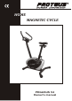
HOME MAGNETIC CYCLE PEGASUS V4 Owner's manual
INDEX . . . . . . . . Introduction / Safety Guideline . . . . . . . . . . . . . . . . . . 01~02 Information . . . . . . . . . . . . . . . . . . . . . . . . . . . . . . . . . 02 Assembly Instruction . . . . . . . . . . . . . . . . . . . . . . . . . 03~04 Exploded View . . . . . . . . . . . . . . . . . . . . . . . . . . . . . . 05 Parts List . . . . . . . . . . . . . . . . . . . . . . . . . . . . . . . . . .
INTRODUCTION / SAFETY GUIDELINE / INFORMATION A. Introduction This owner's manual contains assembly, operation, maintenance and safety information. In the interest of safety, please make certain that you read and understand all the information below. B. Safety guideline a. Read the owner's manual and all accompanying literature. Follow it carefully before using your machine. b. This machine is intended for indoor home use only. It is not designed for commercial use. c.
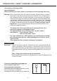
INTRODUCTION / SAFETY GUIDELINE / INFORMATION Information on braking system: Speed-dependent: With increasing speed more power is required to drive the bike and Vice versa. Warning: Before commencing with any exercise program, please consult your family physician. If at any time during exercise you feel faint, dizzy or experience pain, stop and consult your family physician.
ASSEMBLY INSTRUCTION Step 1: Attach the front stabilizer (02) and the rear stabilizer (03) onto the main frame (01). Tighten with carriage bolts (24), washers (28) and dome nuts (32) using spanner supplied. 2 24 3 1 28 24 32 28 32 Step 2. IMPORTANT: READ ALL STEPS BEFORE ATTACHING PEDALS. 18 a. Attach pedal (17&18) to pedal crank. (pedal marked "R" and "L" indicates right and left side of bike. Make sure not to mix it up) b.
ASSEMBLY INSTRUCTION 9 9 11 10 10 FIG.A 26 9 FIG.B 5 9 10 33 11 12 28 25 Step 5: a. Loosen the T-knob (22) from the parts of handlebar post (05). b. Attach handlebar (06) to handlebar post (05) and fix with T-knob (22). Don't over tighten the T-knob before the handlebar located in desired position. c. Adjust the angle of handle by the T-knob (22), tightened the T-knob firmly after adjustment. d.
EXPLODED VIEW 9 9 10 10 15 8 FIG. B FIG.
PARTS LIST NO. DESCRIPTION Q'TY NO.