
Operation Manual

18
7 Adjustment
WARNING
Risk of electric injury.
► Before any manipulation with the tool
make sure to unplug the mains socket
outlet.
7.1 Electronic Motor Control
Starting current limiting
The electronically controlled smooth start
takes care that the machine starts without
jerk. As a result of the machine’s reduced
starting current, a 16 A fuse is suffi cient.
No-load speed reduction
The electronic control reduces the no-load
speed of the machine which results in re-
duced noise and wear of motor and gear.
Constant speed electronics
The constant speed electronics maintains
the speed between no load and load nearly
constant and ensures uniform feeding which
produces an even cutting edge.
Electronic overload protection
In case that the machine is extremely over-
loaded, an electronic overload protection
protects the motor from damage. In this
case, the motor stops and restarts only af-
ter the feeding pressure is reduced, res.
after relief.
Temperature-dependent overload
protection
To prevent overheating under an extreme
long-term load, the safety electronics switch
the motor into cooling mode when the criti-
cal temperature is reached. The machine
cannot be loaded, and it runs at reduced
RPM. After cooling, the tool is once again
prepared for operation and can be fully
loaded in about 3 – 5 minutes. If the tool
gets hot while running, the heat protection
reacts correspondingly earlier.
Speed pre-selection
With the speed control [1-11], the speed
can be continuously pre-selected:
Speed 1: 1800 min
–1
Speed 4: 3000 min
–1
Speed 2: 2200 min
–1
Speed 5: 3400 min
–1
Speed 3: 2600 min
–1
Speed 6: 3800 min
–1
The required speed depends on the saw blade
used and the material to be worked.
Run-on Brake
After releasing the On/Off switch, the in-
tegrated run-on brake stops the saw blade
within approx. 2 seconds.
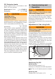
7.2 Cutting Depth Adjustment
Loosen the clamping lever [3-1].
Set the required depth on the cutting depth
scale [3-2].
Raise: smaller cutting depth (Figure [3a])
Lower: larger cutting depth (Figure [3b])
Re-tighten the clamping lever [3-1].
To achieve the best cutting results, the saw
blade should protrude from the material by
no more than 3 mm.
7.3 Cutting Angle Adjustment
Loosen the winged screws [4-2].
Set the cutting depth on the scale [4-3] to
the required value (the cutting angle scale
is marked in 1°-steps).
Re-tighten the winged screws [4-2].
WARNING
The maximum cutting depth is re-
duced for bevel cuts.
7.4 Cutting Edge Indicator
When making right-angled (90°) and bevel
cuts, the cutting edge indicator [4-1] and
the middle of the saw blade are in one line.
During cutting, the edge of the cut indica-
tor aligns in case of cutting with guide rail
(GRP 800/1400/3000-2), with the saw blade
centre at all cutting angles (from 0° to 45°).
In case of cutting without the guide rail the
cutting indicator edge follows the centre of
the saw blade in square cut only.
Follow your marked line with the cutting
edge indicator.
7.5 Parallel Guide
The parallel guide [1-9] is inserted in the
holders on the foot plate [1-7] and secured
with the winged screws [1-12]. The paral-
lel guide makes possible exact cuts along
a workpiece edge or the cutting of parallel
strips. The maximum cutting width is ap-
prox. 120 mm.