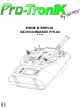
MODE D’EMPLOI RADIOCOMMANDE PTR-6A V 2.
1 DES MATIERES 2 TABLE CARACTERISTIQUES 1 / TABLE DES MATIERES…………….……………………………………………………………………………………………….2 2 / INTRODUCTION….………………………………………………………………………………………………………………….3 3 / CARACTERISTIQUES ..…………………………………………………………………………………………………………….4 EMETTEUR / DISPOSITION DES ORGANES DE COMMANDE.………………………………..5 RECEPTEUR……………………………….…………………………………………………………………………6 4 / INFORMATIONS GENERALES………………………………………………………………………………………………….7 LA BATTERIE DE L’EMETTEUR……………………………………………………………………………….
2 INTRODUCTION Nous vous remercions pour l’achat d’un ensemble de radiocommande PTR-6A Pro-Tronik. Moderne et très performant, cet ensemble est le complément idéal de vos modèles d'avions et de planeurs devant comporter jusqu'à 6 fonctions. Il convient parfaitement au débutant dans le cadre d'un premier achat tout comme au pilote expérimenté à la recherche d'un second ensemble pour les vacances ou le vol indoor par exemple.
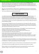
3 2 CARACTERISTIQUES Votre ensemble PTR-6A se compose d'un émetteur, d'un récepteur et de la présente notice. L'EMETTEUR PTR-6A (Ref. : 70100) Appareil digital programmable offrant 6 voies et capable de contrôler efficacement des modèles d'avions ou de planeur. Alimentation sur batterie rechargeable NiMH 4,8 V / 800 mA offrant une sécurité optimale et une autonomie très confortable (supérieure à 8 heures selon le mode d’utilisation et la puissance).
3 2 CARACTERISTIQUES (suite) 3 mixages préprogrammés de type "double ailerons", 'aile delta" et "empennage en vé". Puissance d'émission réglable permettant de réaliser aisément un test de portée ou de voler en intérieur en réduisant la consommation électrique. Possibilité d'alimentation par LiPo 2S. Voie 5 contrôlée par un interrupteur à levier à 3 positions. Voie 6 contrôlée par un interrupteur à levier à 2 positions. Chronomètre contrôlé par un interrupteur à 2 positions.
3 2 CARACTERISTIQUES (fin) LE RECEPTEUR R6X (Ref. : 70216) Appareil digital offrant 6 voies et capable de contrôler efficacement des modèles d'avions ou de planeur. Alimentation sur batterie rechargeable 4,8 V à 8,4 V (LiPo 2S). Protection contre les erreurs de polarité. Consommation électrique réduite optimisant l'autonomie du modèle. Très bonne résistance face aux chutes de tension d'alimentation (fonctionnement assuré jusqu'à 3,15 V).
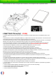
4 GENERALES 2 INFORMATIONS CARACTERISTIQUES 4.1 LA BATTERIE DE L’EMETTEUR Votre émetteur est équipé d’origine d’une batterie NiMH assurant une sécurité optimale d’utilisation ainsi qu’un coût d’utilisation très réduit de votre ensemble. Après avoir lu la notice dans sa totalité, procédez à la charge de la batterie de l'émetteur avec un chargeur appropriée (non fourni).
2 INFORMATIONS CARACTERISTIQUES 4 GENERALES (suite) P P Puissant. Le F Le niveau des ondes émises est réduit. niveau des ondes émises est élevé. Faible. 4.3 POSITIONNEMENT DE L’ANTENNE DU RECEPTEUR La sensibilité de l’antenne du récepteur est similaire à celle de l’émetteur. Les ondes sont reçues de manière optimale sur les côtés de la partie active de l’antenne (partie mesurant 30 mm à l’extrémité de la rallonge noire mesurant environ 11 cm). S Le S niveau des ondes reçues est élevé. Sensible.
2 INFORMATIONS CARACTERISTIQUES 4 GENERALES (fin) Alimentation par une batterie de réception. Une telle batterie d’alimentation est typiquement composée de 4 ou 5 éléments NiMH assemblés en série. Elle délivre une tension comprise entre 5 et 6 V en fonctionnement. La capacité de cette batterie doit être choisie en fonction du nombre et du type de servos que comporte le modèle. Plus ce nombre est important, plus la consommation des servos est importante, et plus la capacité de la batterie doit être élevée.
5 OU « BINDING » ENTRE EMETTEUR ET RECEPTEUR 2 APPAIRAGE CARACTERISTIQUES Votre ensemble de radiocommande Pro-Tronik établit une liaison dans la bande des 2,4 GHz entre l’émetteur et le récepteur. Cette bande dite ISM (Industry, Science and Medical care) n’est pas dédiée aux radiocommandes. Elle est également utilisée par de très nombreux autres appareils tels que le WiFi, le Bluetooth, certains fours, jeux, domotique, etc.
6 TEST DE PORTEE 2 CARACTERISTIQUES Comme n’importe quel ensemble de radiocommande, votre ensemble Pro-Tronik nécessite de réaliser un test de portée avant chaque utilisation sur le terrain. Le test de portée a pour objectif de vérifier que la portée de la liaison, fortement dépendante de la qualité de l’installation à bord du modèle, est assurée en toute circonstance.
7 SYSTEME 2 MENU CARACTERISTIQUES Les fonctionnalités communes de votre émetteur sont regroupées dans le menu SYSTEME, qui donne accès aux deux sous-menus suivants : - Réglage du chronomètre de chaque mémoire de modèle - Réglage de la puissance d'émission de l'émetteur Pour accéder au menu SYSTEME, maintenez la touche ENTER pressée puis mettez simultanément l'émetteur sous tension.
7 SYSTÈME (fin) 2 MENU CARACTERISTIQUES 7.2 REGLAGE DE LA PUISSANCE D’EMISSION Votre émetteur offre un réglage de sa puissance d'émission. Cela permet par exemple de réduire la consommation électrique si vous volez à courte distance (vol indoor) ou encore de réaliser un test de portée sans devoir vous éloigner démesurément de votre modèle.
8 MODE 2 MENU CARACTERISTIQUES Votre émetteur vous permet de définir la répartition des fonctions sur les manches grâce au menu MODE de pilotage. Pour accéder à cette fonctionnalité, maintenez les touches ENTER et EXIT pressées puis mettez simultanément l'émetteur sous tension. Le menu MODE s'affiche alors sur l'écran. 8.1 REGLAGE DU MODE DE PILOTAGE Votre émetteur propose 4 modes de pilotage différents nommés MODE 1 à MODE 4.
9 DE L’EMETTEUR 2 UTILISATION CARACTERISTIQUES Ce chapitre va vous permettre de bien identifier et connaître le rôle de chaque organe de votre émetteur afin de l’exploiter au mieux. 9.1 LES ORGANES DE COMMANDE Les organes de commande permettent de contrôler le vol des modèles grâce aux 6 voies ou fonctions distinctes de votre émetteur. Les 4 voies principales (Ailerons, Direction, Profondeur et Gaz) sont contrôlées par les deux manches.
10 MENU FONCTIONNALITES 2 CARACTERISTIQUES Ce chapitre décrit l’ensemble des fonctionnalités offertes par votre émetteur. Il est important de vous familiariser avec chacune d’elle afin d’en tirer le meilleur profit en toute circonstance. Avant d’entrer en détail dans chacune des fonctionnalités de l’émetteur, nous vous proposons de vous familiariser avec l’écran principal de votre émetteur.
10 MENU FONCTIONNALITES (suite) 2 CARACTERISTIQUES Une fois la touche ENTER pressée, l’écran du menu des fonctionnalités s’affiche ainsi : ENTER 10.1 SELECTION DE LA MÉMOIRE DE MODELE 1/ Depuis l’écran principal, pressez la touche ENTER pendant 3 secondes pour afficher le menu des fonctionnalités. 2/ Pressez l’une des touches UP ou DOWN pour faire défiler les mémoires 1 à 8.
10 MENU FONCTIONNALITES (suite) 2 CARACTERISTIQUES 4/ Pressez la touche EXIT pour sélectionner la voie 2 (CH2) puis répéter les étapes 2 et 3 pour ajuster le débattement des voies 3 puis 4. La touche EXIT permet de sélectionner la voie à régler. 5/ pressez ENTER puis EXIT pour revenir à l’écran principal et utiliser la mémoire de modèle sélectionnée. 10.4 MIXAGES Votre émetteur propose 4 types de mixages différents, repérés par le numéros des voies mixées entre elles.
10 MENU FONCTIONNALITES (fin) 2 CARACTERISTIQUES 1 - 6 mixage Volets donne Ailerons (uniquement si le mixage Flaperons est activé) a/ Depuis l’écran de mixage 1 - 6, pressez la touche EXIT pour accéder au réglage du taux de mixage Volet donne Aileron. EXIT UP/DOWN 3.2/ Pressez la touche UP ou DOWN pour ajuster le taux de mixage Volet donne Ailerons vers le haut ou vers le bas (valeur positive ou négative selon la configuration du modèle).
11 MENU FIN DE COURSES/ EXPONENTIEL 2 CARACTERISTIQUES Votre émetteur propose les fonctionnalités avancées de réglage de Fin de course (End Point) de chaque voie ainsi que d’Exponentiel (Expo), regroupées dans le menu EP:EX. Pour accéder à ce menu, maintenez la touche EXIT pressée puis mettez simultanément l'émetteur sous tension. Le menu EP:EX s'affiche alors sur l'écran, indiquant que vous pouvez régler soit les fins de courses de chaque voie, soit la courbe de réponse des 3 axes (voies 1, 2 et 4).
12 CONFIGURATION DU MODE PPM DU RECEPTEUR 2 CARACTERISTIQUES Il existe sur le marché des matériels utilisant un signal PPM positif (c’est le cas de votre ensemble Protronik) et d’autres utilisant un signal PPM négatif. Afin d’offrir une compatibilité la plus large possible, notamment pour l’écolage sans fil, votre récepteur propose les deux types de polarité au choix.
13 MENU MAINTENANCE 2 CARACTERISTIQUES 13.1 CHANGEMENT DE L’ID DE L’EMETTEUR i Afin d’éviter tout phénomène de brouillage entre émetteurs et récepteurs, chaque émetteur est livré préconfiguré a avec un numéro d’identification attribué en usine, qui lui permet d’être reconnu lors de la procédure d’appairage avec le récepteur. Il peut arriver que deux émetteurs soient dotés du même ID.
14 GARANTIE ET SAV 2 CARACTERISTIQUES 14.1 GARANTIE Votre ensemble de radiocommande les a été fabriqué selon les méthodes les plus modernes et avec le plus grand soin. La garantie d’une durée de 12 mois à compter de la date d’achat figurant sur la facture couvre exclusivement une panne survenant durant cette période dans le cadre d’une utilisation normale des produits. Cette analyse des conditions d’utilisation sera menée par notre SAV qui sera seul juge en la matière.
ANNEXE ECOLAGE : RAPPELS INTRODUCTION Cette annexe a été créé afin de répondre aux très nombreuses questions d’utilisateurs concernant la mise en œuvre pratique de l’ensemble de radiocommande PTR-6A dans le cadre d’un système d’écolage. Il décrit les grands principes de cette fonctionnalité, les conditions et limites d’utilisation de l’ensemble PTR-6A ainsi que quelques exemples concrets de mise en œuvre.
ANNEXE ECOLAGE : RAPPELS 2 CARACTERISTIQUES - ECOLAGE FILAIRE il consiste à relier les deux émetteurs Maître et Elève par un cordon d’écolage spécifique dont les connecteurs des deux extrémités sont respectivement compatibles avec les deux références d’émetteur. Les signaux électriques des deux émetteurs doivent également être compatibles (polarité, niveau et nombre de voies notamment).
ANNEXE ECOLAGE : MISE EN ŒUVRE PRATIQUE 2 CARACTERISTIQUES ! i AVERTISSEMENT : afin d’éliminer tout risque de blessure, il est indispensable de démonter temporairement l’hélice de l’avion école avant tout essai ou réglage d’écolage. Ceci est totalement incontournable si le modèle école est doté d’un moteur électrique. Votre émetteur PTR-6A, qu’il soit classique ou en V2, peut à priori être utilisé comme émetteur Elève dans le cadre d’un système d’écolage sans fil.
ANNEXE ECOLAGE : CORDONS D’ECOLAGE 2 CARACTERISTIQUES Vers connecteur DSC TX Graupner 3 2 MASSE SIGNAL (1) 1 TIP X SIGNAL PPM (3) Vers connecteur BAT/PPM R6X V2 CORDON D'ECOLAGE SANS FIL PROTRONIK - GRAUPNER* *Testé avec un émetteur mx-20 Hott Vers connecteur DSC TX JR Propo 3 2 MASSE SIGNAL (1) 1 TIP X SIGNAL PPM (3) Vers connecteur BAT/PPM R6X V2 CORDON D'ECOLAGE SANS FIL PROTRONIK - JR PROPO* *Testé avec un émetteur XG11 Vers connecteur DSC TX Spektrum 3 2 MASSE SIGNAL (1) 1 X TIP S
ANNEXE ECOLAGE : CORDONS D’ECOLAGE 2 CARACTERISTIQUES Vue côté soudure du connecteur mâle 2 Vers connecteur TX Multiplex 4 5 MASSE SIGNAL (3) 1 3 X SIGNAL PPM (4) Vers connecteur BAT/PPM R6X V2 CORDON D'ECOLAGE SANS FIL PROTRONIK - MULTIPLEX Vue côté soudure du connecteur mâle 2 Vers connecteur TX Multiplex (nouvelle génération) 4 5 1 MASSE SIGNAL (3) 3 6 7 X SIGNAL PPM (4) Vers connecteur BAT/PPM R6X V2 CORDON D'ECOLAGE SANS FIL PROTRONIK - MULTIPLEX* *Testé avec un émetteur ROYAL PRO tm
USER MANUAL PTR-6A Transmitter V 2.
1 TABLE OF CONTENTS 2 CARACTERISTIQUES TABLE OF CONTENTS………………………………………………………………………………………………………………….30 INTRODUCING…………………………………………..……………………………………………………………………………….31 FEATURES……………………………………………………………….………………………………………………………………….32 Tx………………………………………………………………………………………………………………………..32 Tx diagram….……………………………………………………………………………………………………….33 Rx………………………………………………………………………………..………………………………………34 OVERALL FEATURES…………………………………………………………………………………………………………………….35 Tx battery……………………………………………….
2 INTRODUCING the PTR-6A We woud like to thank you for buying a PTR-6A Pro-Tronik Remote control set. Up to date and efficient, this set is the perfect addition to your model airplanes and gliders having up to 6 functions. It is suitable for beginners through an initial purchase as well as the experienced pilot looking for a second set for the holidays or indoor flight for example. We recommend that you carefully read this manual before operating your PTR-6A set.
3 2 FEATURES CARACTERISTIQUES Your PTR-6A set consists of a transmitter, a receiver and this manual. The PTR-6A Transmitter (#70100) Digital programmable transmitter with 6-channel able to effectively control model airplanes or gliders. Rechargeable 4.8 V / 800 mA NiMH Battery offering optimum security and a very comfortable autonomy (more than 8 hours depending on the operating mode and power). Emission in the 2.
3 2 FEATURES CARACTERISTIQUES 3 pre-programmed mixes "double ailerons" delta wing "and" V-tail ". Adjustable transmission power to achieve easily range test or fly indoor reducing power consumption. 2S LiPo possible for power supply. Channel 5 is controlled by a 3 positions switch. Channel 6 is controlled by a 2 positions switch. Timer is controlled by a 2 positions switch. Dual Rate is controlled by a 2 positions switch.
3 2 FEATURES CARACTERISTIQUES R6X Receiver (#70216) Digital receiver with 6-channel able to effectively control model airplanes or gliders. Power supply from 4,8 V to 8,4 V (2S LiPo). Reverse polarity protection. Very low Amp draw. Very good resistance to voltage drops (insured up to 3.15 V operation). Very low reboot delay in case of loss of power. Receiving in the 2.
4 FEATURES 2 OVERALL CARACTERISTIQUES 4.1 TRANSMITTER BATTERY Your transmitter is equipped with a NiMH battery ensuring optimum safety of use and a very reduced cost of ownership of your set. After reading the manual in its entirety, charge the Tx battery with a suitable charger (not supplied). To perform this operation : 1/ Open the battery bay 2/ Get the free connector running out of the battery 3/ Connect the battery to the charger. We recommend to use the simple A2Pro 7200 or 7220 chargers.
2 OVERALL CARACTERISTIQUES 4 FEATURES S S Strong. Level of W Level of emitted waves is low. emitted waves is high. Weak. 4.3 RECEIVER ANTENNA POSTION The sensitivity of the receiver antenna is similar to the transmitter antenna. The waves are received optimally on the sides of the active part of the antenna (part measuring 30 mm at the end of the black extension measuring about 11 cm). S « ACTIVE » Part « EXTENSION » part S W W Sensitive. Level of received waves is high. Weak.
2 OVERALL CARACTERISTIQUES 4 FEATURES Rx battery power supply. Such a battery pack is typically composed of 4 or 5 NiMH cells assembled in series. It supplies a voltage of between 5 and 6 V in operation. The capacity of this battery should be chosen depending on the number and type of servos involved in the model. The higher the number, the greater the consumption of servos is important, and the battery capacity must be high.
5 PROCEDURE 2 BINDING CARACTERISTIQUES Your Pro-Tronik radio control system establishes a connection in the 2.4 GHz band between the transmitter and the receiver. This band called ISM (Industry, Science and Medical care) is not dedicated to remote controls. It is also used by many other devices such as WiFi, Bluetooth, some ovens, games, home automation, etc.. This implies that the range of your set can be greatly reduced in town or in an environment "polluted" by these waves.
6 TEST 2 RANGE CARACTERISTIQUES Like any radio control system, set your Pro-Tronik requires to perform a range check before each use in the field. The range test is intended to verify that the scope of the connection heavily dependent on the quality of the installation on the model is ensured at all times.
7 MENU 2 SYSTEM CARACTERISTIQUES Common features of your transmitter are grouped in the SYSTEM menu, which gives access to two sub-menus: - Setting the timer for each model memory - Adjusting the transmit power of the emitter To access the System Menu, maintain ENTER button pressed and turn the transmitter on. The System Menu appears on the screen, indicating that you can set either the timer (Timer letter T), or power (letter P for Power).
7 MENU 2 SYSTEM CARACTERISTIQUES 7.2 SETTING THE EMITTING POWER Your transmitter offers adjusting its transmission power. This allows for example to reduce power consumption if you fly short distances (indoor flight) or to perform a range check without having to move away your model disproportionately. SETTING PROCEDURE 1/ maintain ENTER button pressed and turn the transmitter on 2/ Once in the SYSTEM menu, press the EXIT button to enter the POWER sub-menu.
8 MODE SETTING 2 STICK CARACTERISTIQUES Your transmitter allows you to define the distribution of functions with the MODE menu. To access this feature, hold the ENTER and EXIT keys pressed simultaneously then turn the transmitter on. The MODE menu is displayed on the screen CONTROL MODE SETTING Your transmitter offers 4 different control modes named MODE 1 to MODE 4.
9 YOUR TRANSMITTER 2 USING CARACTERISTIQUES This chapter will help you to clearly identify and understand the role of each organ of your transmitter to exploit it at best. 9.1 STICKS The control organs used to control the flying models due to the 6 channels or distinct functions of your transmitter. The four main channels (Ailerons, Rudder, Elevator & Throttle) are controlled by two sticks.
10 FUNCTIONS 2 CARACTERISTIQUES This chapter describes all the features offered by your transmitter. It is important to familiarize yourself with each of them in order to get the best in all circumstances. Before entering in detail every feature of the transmitter, we suggest you familiarize yourself with the main screen of your transmitter.
10 FUNCTIONS 2 CARACTERISTIQUES Once the ENTER key is pressed, the menu screen is displayed and features : ENTER 10.1 MEMORY SELECTION 1/ From the main screen, press the ENTER button for 3 seconds to display the features menu. 2/ Press one of the UP or DOWN keys to scroll through the 1 to 8 memory. 3/ Once the desired memory number is displayed, press ENTER and EXIT to return to the main screen and use the selected model memory. UP/DOWN 10.
10 FUNCTIONS 2 CARACTERISTIQUES 4/ Press the EXIT button to select channel 2 (CH2) and repeat steps 2 and 3 to adjust the travel of channels 3 and 4. EXIT button to select the channel to be adjusted. 5/ press ENTER and then EXIT to return to the main screen and use the selected model memory. 10.4 MIXES Your transmitter offers 4 types of different mixes, identified by the numbers of the mixed channels. 1/ From the main screen, press the ENTER button for 3 seconds to display the features menu.
10 FUNCTIONS 2 CARACTERISTIQUES 1 – 6 Flaps to Ailerons mix (Only when the FLAP mix is enabled) a/ From the 1 – 6 mix screen, press the EXIT button to enter the flaps to Aileron mixing ratio setting. EXIT UP/DOWN 3.2/ Press UP or DOWN to adjust the mixing ratio upward or downward (positive or negative depending on the model configuration).
11 END POINT / EXPONENTIAL MENU 2 CARACTERISTIQUES Your transmitter offers advanced control features of end point of each channel as well as exponential, grouped in the menu EP:EX. To access this menu, press the EXIT button pressed simultaneously and turn the transmitter on. EP:EX menu will appear on the screen indicating that you can adjust end point for each channel or the response curve of the 3 axes (channels 1, 2 and 4).
12 PPM MODE RECEIVER CONFIGURATION 2 CARACTERISTIQUES It exists on the market transmitter using a positive PPM signal (so your Protronik together) and others using a negative PPM signal. In order to offer the widest compatibility, especially for wireless schooling, your receiver offers both types of polarity. In both cases, the receiver offers simultaneously on the BATT/PPM connector PPM signal of the requested polarity and channel signals CH1 to CH6 to the corresponding connectors.
13 MAINTENANCE MENU 2 CARACTERISTIQUES 13.1 CHANGING TRANSMITTER’S ID To avoid interference phenomenon between transmitters and receivers, each transmitter comes preconfigured with a an identification number assigned at the factory, allowing it to be recognized during the pairing procedure with the receiver. It may happen that two transmitters are provided with the same ID. When such a situation occurs, the two transmitters sharing the same ID can control the same receiver with which one of them was paired.
14 WARRANTY AND AFTER SALE SERVICE 2 CARACTERISTIQUES 11.1 WARRANTY Your Pro-Tronik radio control system was manufactured according to the most modern methods and with the utmost care. The warranty for a period of 12 months from the date of purchase on the invoice only covers failures occurring during this period under normal use of the products. This analysis of the conditions of use led by our customer service will be the sole judge in the matter.
ANNEX TRAINERS : REMINDER INTRODUCTION This annex was created to address the many questions of users about the practical implementation of all PTR-6A radio as part of a schooling system. It describes the main principles of this feature, the conditions and limits of use of the PTR-6A whole and some concrete examples of implementation. CAUTION This document can never be a substitute for instructions and manuals of the relevant devices. Similarly, it can in no way be considered exhaustive or 100% reliable.
ANNEX TRAINERS : REMINDER 2 CARACTERISTIQUES - WIRED TRAINER It involves linking the two transmitters master and student by a cord specific schooling with connectors on both ends are respectively compatible with both transmitter references. -The electrical signals of the two transmitters must also be compatible (polarity, level and number of such channels). STUDENT TX MASTER TX WIRED TRAINER - WIRELESS TRAINER no cord physically and electrically connects both master and student transmitters.
ANNEX TRAINER : PRACTICAL IMPLEMENTATION 2 CARACTERISTIQUES ! WARNING : to eliminate any risk of injury, it is necessary to temporarily dismantle the propeller of the aircraft school before any test or trainer adjustment. This is totally unavoidable if the school model has an electric motor. Your transmitter PTR-6A, whether classical or V2, can be used as student transmitter for a i wireless schooling trainer.
ANNEX TRAINER : SCHOOLING CORD 2 CARACTERISTIQUES SCHOOLING LEAD STUDENT R6X V2 MASTER TX RX BATTERY WIRELESS SCHOOLING TRAINER CONNECTION PRINCIPLE To DSC TX Graupner Vers connecteur connector DSC TX Graupner 3 2 GROUND SIGNAL MASSE SIGNAL (1) (1) 1 TIP X SIGNAL PPM(3) (3) PPM SIGNAL To BAT/PPM R6X V2 Vers connecteur connector BAT/PPM R6X V2 WIRELESS SCHOOLING CORD PTR-6A – GRAUPNER* CORDON D'ECOLAGE SANS FIL PROTRONIK - GRAUPNER* * Tested Hottmx-20 transmitter *Testé avecwith un mx-20 émetteu
ANNEX TRAINER : SCHOOLING CORD 2 CARACTERISTIQUES view solder side of the Vue côté soudure male connector du connecteur mâle 2 To TXconnecteur Multiplex Vers connector TX Multiplex 4 5 GROUND SIGNAL (1) MASSE SIGNAL (3) 1 3 X SIGNAL PPM (4) (4) PPM SIGNAL To BAT/PPM R6X V2 Vers connecteur connector BAT/PPM R6X V2 CORDON D'ECOLAGE SANS FIL PROTRONIK - MULTIPLEX WIRELESS SCHOOLING CORD PTR-6A – MULTIPLEX view solder side of the Vue côté soudure male connector du connecteur mâle To TX Multiplex Vers