Providence Rail Installation Instructions instructions-Extra-Pages-042015.
Important Information about the Providence Rail System The Providence Rail system utilizes pre-marked dimples to assist in locating the balusters for equal spacing. Dimples are used rather than pre-drilled holes to give you the flexibility to use the pre-marked standard locations or to determine your own baluster locations. In addition, an Assembly Jig kit is available to assist in locating the balusters and positioning them properly for attaching the screws.
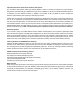
RS70 Providence Rail System Installation Instructions 6' Rail Cap 1 1 1 2 2 2 Upper & Lower Reinforcement 2 2 2 Level Rail Brackets 4 4 4 Stair Rail Brackets - Upper 2 2 2 2 2 2 13 18 23 1 2 3 16 16 16 10 10 10 31 44 55 13 18 23 0 0 4 Common Rail (as used at top & bottom of balusters) (Included with Stair Rail Kits Only) Stair Rail Brackets - Lower (Included with Stair Rail Kits Only) Baluster 1-1/4" square 30" or 36" length Crush Block 1-1/4" Square x 4" Ⓐ 🅐
RS70 Providence Rail System Installation Instructions Level Rail Section Application (NOTE: for 3-Line Rail, read Section 5 first before starting at Section 1) 1. Measure to determine baluster layout, cut rail sections to length. a. Ensure newels or columns to which rail will be mounted are plumb and sturdy enough to support rail. If newel/column covers are used, ensure they have blocking at each location where railing will be attached. b. Measure span at top and bottom rail locations. c.
RS70 Providence Rail System Installation Instructions e. Drill one additional 3/16” hole at each end of the bottom Aluminum Rail Reinforcement for drainage. 4. Install rail a. Position bottom Aluminum Rail Reinforcement, with crush block(s) attached, between newels or columns, centered in newel or column face, and secure each end with two rail attachment screws 🅑. b. Position PVC rail/baluster assembly between newels or columns and seat fully down on bottom aluminum rail reinforcement. c.
RS70 Providence Rail System Installation Instructions Level Rail Section Application with Glass Balusters. Note: Glass Baluster application requires the RS70 Providence series rail sets specifically prepared for the Glass Balusters, along with the appropriate quantities of balusters (sold separately in packs of 5). Measure to determine baluster layout, cut rail sections to length. a. Ensure newels or columns to which rail will be mounted are plumb and sturdy enough to support rail.
RS70 Providence Rail System Installation Instructions f. Ensure rail is centered on face of newel or column and secure each end with two rail attachment screws 🅑. g. Drill a 3/16” hole down through the aluminum reinforcement and the Top Common Rail between the first and second baluster at both ends and near the center of the span (all between balusters). Countersink holes from underside of the Top Common Rail for a #8 Screw to ensure that screw seats flush with PVC and to prevent stripping. h.
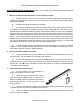
RS70 Providence Rail System Installation Instructions 3. Prepare aluminum reinforcements. Lower Stair Bracket a. Attach a Lower Stair Bracket (90-degree bend) using two rail bracket screw 🅐 to the lower end of each reinforcement. Lubricate the threads with soap to avoid binding and use a clutch type drill to avoid stripping screws. Note: Do not cut this end of the reinforcement to the rake angle. Upper Stair Bracket b.
RS70 Providence Rail System Installation Instructions Special Applications/Situations. Note: the following situations are not CCRR compliant. Rail to Newel connections at an angle This method can be used for angled rail connections to newels, up to a 45 degree angle. • Determine length and angles for connections to newels at both ends. Cut PVC common rails to fit, remembering orientation of common rail before cutting (one up, one down).
RS70 Providence Rail System Installation Instructions • Intex offers 45 degree and 90 degree directional change brackets (sold separately). These can be used to change rail direction within the span, while leaving the connections to the newel(s) flush. Two brackets are required (one for the top rail, one for the bottom rail). Item #’s RS7045BKT and RS70-90BKT.
RS70 Providence Rail System Installation Instructions RS70INST-1 (05/06/2019)