PROVISION-ISR DAI-310IPVF I4-310IPVF DAI-390IPVF I4-390IPVF BX-390IP DAI-380IPVF I4-380IPVF BX-380IP User Manual IP Camera For H.
Notes Before operation, we strongly advise users to read this manual and keep it for later use. Please use the specified power supply to connect. Avoid from incorrect operation, shock vibration, heavy pressing which can cause damage to product. Do not use corrosive detergent to clean main body of the camera. If necessary, please use soft dry cloth to wipe dirt; for hard contamination, use neutral detergent. Any cleanser for high grade furniture is applicable.
IP CAMERA USER MANUAL Table of Contents 1 2 Introduction.........................................................................................................1 IE Remote Access .................................................................................................2 2.1 2.2 3 4 LAN ................................................................................................................................... 2 2.1.1 Access through IP-Tool................................................
IP CAMERA USER MANUAL 5 User Configuration ............................................................................................. 26 4.6.2 Security Configuration........................................................................................ 28 4.6.3 Configure Backup & Restore ............................................................................... 28 4.6.4 Reboot Device ................................................................................................... 29 4.6.
Page 1 1 IP CAMERA USER MANUAL Introduction This IP-CAMERA (short for IP-CAM) is designed for high performance CCTV solutions. It adopts state of the art video processing chips. It utilizes most advanced technologies, such as video encoding and decoding technology, complies with the TCP/IP protocol, SoC, etc to ensure this system more stable and reliable. This unit consists of two parts: the IP-CAM device and central management software (short for CMS).
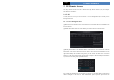
Page 2 IP CAMERA USER MANUAL 2 IE Remote Access You may connect IP-Cam via LAN or WAN. Here only take IE browser (6.0) for example. The details are as follows: 2.1 LAN In LAN, there are two ways to access IP-Cam: 1. Access through IP-Tool; 2. Directly access through IE browser. 2.1.1 Access through IP-Tool ① Make sure the PC and IP-Cam are connected to the LAN and the IP-Tool is installed in the PC from the CD.
Page 3 IP CAMERA USER MANUAL administrator and click “Modify” button to modify the setting. The default password of the administrator is “123456”. ④ Double click the IP address and then the system will pop up the IE browser to connect IP-CAM. IE browser will auto download the Active X control. After downloading, a login window will pop up as shown below. Input the username and password to log in. The default username is “admin”; the default password is “123456”. 2.1.
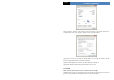
Page 4 IP CAMERA USER MANUAL Select “Property” and then select internet protocol according to the actual situation (for example: IPV4). Next, click “Property” button to set the network of the PC. ② Open the IE browser and input the default address of IP-CAM and confirm. The IE browser will download Active X control automatically. ③ After downloading Active X control, the login dialog box will pop up. ④ Input the default username and password and then enter to view. 2.
Page 5 IP CAMERA USER MANUAL ② Go to Config Network ConfigIP Address menu to modify the IP address. ③ Go to the router’s management interface through IE browser to forward the IP address and port of the camera in the “Virtual Server”. Port Setup IP Setup Router Setup ④ Open the IE browser and input its WAN IP and http port to access.
Page 6 IP CAMERA USER MANUAL 3 Remote Preview 3.1 The Remote Preview Interface Icon Description Motion alarm indicator icon Fix size Actual size Zoom in Icon Description Sensor alarm indicator icon Start/Stop record Playback Snap Zoom out Talk Full screen Enable audio When motion detection alarm is triggered, the people icon will turn red. Right click to pop up a pull-down list as shown below: Stream: Three streams are optional.
Page 7 IP CAMERA USER MANUAL view the image from every direction by controlling PTZ panel. The descriptions of the control panel are as follows: Button Description to rotate the dome upwards; the dome towards left; diagonally up-left;; diagonally down-left; to rotate the dome downwards; to rotate to rotate the dome towards right; to rotate the dome to rotate the dome diagonally up-right; to rotate the dome to rotate the dome diagonally down-right; to stop rotating the dome.
Page 8 IP CAMERA USER MANUAL 4 Forward 8 Zoom in 12 Volume 3.3 Snap Pictures Select the picture number, and then click “Snap” icon as shown below: Single Snap Snap multiple pictures Select the picture number from Frame pull down list box, such as 2, and check “Title” and “Time” to show capture title and time on the snap pictures simultaneously.
Page 9 IP CAMERA USER MANUAL 4 Remote Live Surveillance Functions of remote configurations include: System Configuration, Video Configuration, PTZ Configuration, Alarm Configuration, Network Configuration and Advanced Configuration. You should firstly select the menu on the left, and then set up the relative parameters. When one user configures parameters of a certain device, other users can not set up this device. 4.
Page 10 IP CAMERA USER MANUAL 4.1.2 Date & Time Configuration Setting steps: 1. Go to ConfigDate & Time menu as shown below. 2. Set time zone. 3. Enable DST mode as required. 4. Set time. You may set time manually or enable NTP. 4.1.3 SD Card 1. Go to “System Configuration” “SD Card” as shown below: The first time you used the SD card, you should click “Format SD card”. Click “Eject card” to stop writing data to SD card. Then the SD card can be ejected safely.
Page 11 IP CAMERA USER MANUAL 4.2.1 Camera Configuration Setting steps: 1. Go to “Video Configuration” “Camera” interface as shown below. 2. You may adjust brightness, contrast, hue and saturation of the picture. 3. Select white balance mode. 4. Wide dynamic, sharpen, and denoise are adjustable. 5. You can also set day-night mode and enable the image mirror and image overturn function. 6. You may frequency and repair bad pixel. 7. Press the “Save” button to save the settings. 4.2.
Page 12 IP CAMERA USER MANUAL video resources. This will help to optimize the network bandwidth. Video Quality: When VBR is selected, you need to choose image quality. The higher the image quality you choose, the more bitrate will be required. Bitrate: Please choose it according to the actual network situation. I Frame interval: It is recommended to use the default value. If the value is over high, the read speed of the group of pictures will be slow resulting in the quality loss of the video.
Page 13 IP CAMERA USER MANUAL To set up video mask 1. Enable video mask and select mask color. 2. Click “Draw” button and then drag the mouse to draw the video mask area. 3. Click “Save” button to save the settings. 4. Return to the live to see the following picture. Clear the video mask: Go to video mask menu and then click “Clear” button to delete the current video mask area. 4.2.5 ROI Configuration To set up ROI 1. Go to ConfigROI Config menu.
Page 14 IP CAMERA USER MANUAL 2. Check “Enable” and then click “Draw” button. 3. Drag the mouse to set the ROI area. 4. Set the level. 5. Click “Save” button to save the settings. Now, you will see the selected ROI area is clearer than other areas especially in low bitrate condition. 4.3 PTZ Configuration PTZ Configuration includes two submenus: Protocol and Preset. 4.3.1 Protocol 1.
Page 15 IP CAMERA USER MANUAL 2. Input the protocol, address and baud rate according to the speed dome. 4.3.2 Preset Configuration 1. Go to “PTZ Configuration” “Preset” to see an interface as shown below: Button Meanings to rotate the dome upwards; to rotate the dome towards left; to rotate the dome downwards; to rotate the dome towards right; to stop rotating the dome. Focus button. Click button to have long focus; click button to have short focus. Zoom button.
Page 16 IP CAMERA USER MANUAL 4.4 Alarm Configuration Alarm configuration includes six submenus: Motion Detection Area, Motion Detection Trigger, Motion Detection Schedule, Alarm Input Trigger, Alarm Input Schedule and Alarm Out. 4.4.1 Motion Detection Area 1. Go to “Alarm configuration” “Motion Detection Area” to see an interface as below. 2. Move the “Sensitivity” scroll bar to set up the motion trace sensitivity. 3.
Page 17 IP CAMERA USER MANUAL 3. Set alarm holding time. 4. Set alarm trigger options. Alarm Out: If selected, this would trigger the external relay output on detecting a motion based alarm. Trigger Snap: If selected, the system will snap images on an alarm and save them in SD card. Trigger Email: If the email and attach picture checkbox is checked (Email address shall be set first in the Mail config interface), the triggered snap pictures and event will be sent into those address.
Page 18 IP CAMERA USER MANUAL 4.4.4 Alarm Input Trigger 1. Enter “Alarm Configuration” “Alarm Input Trigger” to see a screen as shown below: 2. Select the sensor at the “Sensor” pull down list and set the sensor name and alarm type: NO and NC. 3. Enable alarm and select alarm holding time. 4. Set alarm trigger options. The setting steps are the same as that of motion detection trigger. Please refer to motion detection trigger chapter for details. 5.
Page 19 IP CAMERA USER MANUAL 1. Select the sensor. 2. The following setup steps are similar to Motion Detection Schedule’s. Please refer to Motion Detection Schedule chapter for more details. 4.4.6 Alarm Out 1. Go to “Alarm configuration” “Alarm output” as shown below: 2. Select alarm holding time and alarm name at the “Alarm out” and “Alarm holding time” pull down list box respectively. 3. Press the “Save” button to save the settings. 4.
Page 20 IP CAMERA USER MANUAL device. 4. PPPoE: User needs to manual input the user name and password for dial-up internet. Firstly, log in IE clients and then enter user name and password of PPPoE, save the setting and exit. Secondly, set up IP address change notice. Thirdly, connect with Modem. Then the device will dial up internet automatically. 5. Press the “Save” button to save the settings. 4.5.3 Server Configuration Go to “Network Configuration” “Server Config”. 1.
Page 21 IP CAMERA USER MANUAL changed, a new IP address will be sent to the appointed mailbox automatically; If “FTP” is selected, when the IP address of the device was changed, a new IP address will be sent to FTP server. 4.5.5 DDNS Configuration 1. Domain name Registration (http://provision-isr-dns.com) Note: DDNS is used to register for a hostname with DDNS username and password.
Page 22 4) IP CAMERA USER MANUAL If there is no problem with the domain registration you will see the following message: “Your domain was successfully created.” If you do not see this message, the domain name you requested is already in use and you will be requested to provide an alternate domain name (please note: domain name is sometimes called host name).
Page 23 IP CAMERA USER MANUAL 1. Apply the Domain Name (Take dns2p for example) (1) Register in the Web Register dialog box Step 1: Fill in the blank of IE address with ‘www.dns2p.com’. Step 2: Click to enter the website. Step 3: Click "New User" in the right of homepage to register. For example: User ID is ‘abc’, and password is ‘123456’. The register dialog display as above. (2) Login Step 1: Return to homepage after registering successfully.
Page 24 IP CAMERA USER MANUAL Step 3: Click "Submit" button, the system will pop up a dialog box to show that the domain is added successfully. Note: Time of probationary period is one month. If user wants to use it continuatively after one month, please Step 4: click "Buy Now" in the right of homepage to pay for it. 2. Setup in the IP-CAMERA ⑴ DOMAIN Domain is set in ‘1. Apply the Domain Name’. According to the example above, the domain is ‘WWW. IP-CAMERA.dns2p.com’.
Page 25 IP CAMERA USER MANUAL 3. RTSP Address: The RTSP address you need to input in the media player. 4. You can also choose to enable anonymous viewer login. 4.5.7 UPnP Go to “Network Configuration” “UPnP” interface as shown below. Select “Enable UPnP” and then input friendly name. Then double click “Network” icon on the desktop of the PC to see an icon with the friendly name and IP address of the camera. You may quickly access the device by double clicking this icon. 4.5.
Page 26 IP CAMERA USER MANUAL 4.5.9 FTP Go to Network ConfigurationFTP interface as shown below. 1. Add: Click Add button to input FTP server’s server name, address, port number, user name, password, and upload path, click OK to confirm the setting. 2. Modify: Click this button to change some information of the FTP server. 3. Delete: Select certain FTP account and click this button to delete this account. 4. Test: Select certain FTP account and click this button to test its validity.
Page 27 IP CAMERA USER MANUAL User Configuration Add User Note: After binding physical address to the IP-CAM, you can access the device on this PC in network only. If the MAC address was “00:00:00:00:00:00” which means it can be connected to any computers. 2. Input user name in “User Name” textbox (only letters). 3. Input characters in “Password” and “Confirm Password” textbox (letters or numbers). 4. Input the MAC address of the PC in “Binding MAC address” textbox. 5.
Page 28 IP CAMERA USER MANUAL Parameter Meaning User Name User name to operate the logon client end User Type Type of users, normal user, advanced user and super administrator Binding MAC address The MAC addresses of user access the server which should set up according to actual MAC address of server. Password Password to log in the client terminal Confirm Password Password to log in the client terminal 4.6.2 Security Configuration 1.
Page 29 IP CAMERA USER MANUAL You can import or export the setting information from PC or to device. 1. Click “Browse” to select save path for import or export information on PC. 2. You can import or export all setting information to PC, but those two settings “User Configuration” and “Network Configuration” are exceptional. Default Configuration Click “Load default” button to restore all system settings to the default status. 4.6.
Page 30 IP CAMERA USER MANUAL 5 Mobile Surveillance This IP-CAM supports mobile surveillance by phones with Windows mobile, iPhone, Android and Blackberry OS. Please check the operation system version of mobile before use; and connect the IP-CAM to Internet. 5.1 Network Configuration Access device via LAN Step 1: Connect device via wireless router. Then checkmark DHCP both in router and device to automatically acquire IP address or enter the IP address manually.
Page 31 IP CAMERA USER MANUAL figure on the left. Step2: Search “Provision Cam” and click “Free” button as shown in the figure on the right. Step 3: Click “Install App” button as shown in the figure on the left. Step 4: Input iTunes Store password and then click “OK”. The software will be installed automatically. Install Software through PC Step 1: Install iTunes store in PC and then login. Step 2: Connect iPhone and PC. Step 3: Search and select “Provision Cam”. Step 4: Click “Download” button.
Page 32 IP CAMERA USER MANUAL 3G, normal video quality compared to the former network type. Step 2: Input server, account and password. Server: WAN IP address (or domain name) plus HTTP port of the device. For example: 210.21.183:89 or 123.dvrdydns.com:89. Note: The default http port of the device is 80. If modified, use the modified port. Account and Password: The login account and password of the device. The default account is admin and the default password is 123456.
Page 33 IP CAMERA USER MANUAL : Open/Close audio. Choose the channel and click this button to open/close the audio of this channel. :Open/Close talk. Click this button to pop up the servers which support talk function. Select the device to start talking. :Set video parameter button. Select the channel and click this button to set the video parameters including brightness, hue, saturation and contrast. :PTZ button. Click this button to pop up PTZ control panel.
Page 34 4. IP CAMERA USER MANUAL Live Preview Once you access the device, the system will automatically display the screen mode in accordance with the channel number of the device Note: The maximum number of channels which can be connected are nine after login. 1. Click “Screen mode” button to select channel as shown in Fig 1. 2. When there is video playing in a screen, you can switch the channel by long pressing the screen as shown in Fig 2. 3.
Page 35 IP CAMERA USER MANUAL Fig 4 5. CMS Function This function makes multi-device managements and preview come true. Step 1: Click to enable CMS function. When this icon turns green, it means this function is enabled. Step 2: Click to choose channel as shown in the right picture. After you choose the channel, click “ok”, the system will display the related image automatically. If channels have been added into the group, you can see the images by clicking the group name.
Page 36 IP CAMERA USER MANUAL Enable CMS function and enlighten the group to save the favorite groups as shown in the following picture on the right. Then click button to play. Only one favorite group can be collected. :Color means the channel or group has been collected. Grey means the channel or group isn’t collected. 7. Playback Interface Click “Playback” button to enter the playback interface. Then click “Search” button to search the file. To play the record by click this file name. 8.
Page 37 IP CAMERA USER MANUAL Step 3: Press “Install” button. Step 4: Install the software subject to the notes. Once the downloading is done, the software will install automatically Login Menu Step 1: Configure the network of your device and mobile phone. Step 2: Input the WAN IP address/domain name and port of your device in the sever column. The port should be HTTP port of your device. The default http port of the device is 80. If you have changed your http port, please enter the new port here.
Page 38 IP CAMERA USER MANUAL Record Playback: Click “Playback” in the main menu interface to enter playback interface. Then choose the channel you want to playback. This will take you to see the record file. Click this file to play. Pause/Play Stop Forward Backward Server List: In the main menu interface, click “Server list” to see the above picture on the left hand. Add Server: Click button to pop up a window as shown in the above picture on the right hand.
Page 39 IP CAMERA USER MANUAL this interface, you can set favorite channel and storage. Favorite Channel: Check the favorite channels and click “Save” button to save these channels. Then go into live interface and click button to play these favorite channels. Storage: Setup the relevant parameters of mobile video. Information View: view the DVR/NVR basic information as shown in the picture on the right. 6 IP-Tool Updating through IP-Tool Note: Do not cut off power supply and internet when updating.
Page 40 IP CAMERA USER MANUAL When upgrading the software and kernel, the IP address of PC and device should be at the same network segment. If the network segment is different, user should change the IP address by right clicking the device and then select “network setup”. Modify IP address dialog box will appear as follows: Modify IP address and click OK button to exit the dialog box. After that, IP-Tool will display the new IP address.
Page 41 IP CAMERA USER MANUAL After finishing upgrading, a massage box will pop up as below: Click OK button to exit the update dialog box, and then the device will restart automatically. Select the device and right click it to select “Update kernel”. This will bring up a dialog box as below: Input the relevant information and click “Browse” button to choose your update file. After that, click “Update Kernel” button to start updating.
Page 42 7 IP CAMERA USER MANUAL Q &A 1. Q: How to find my password if I forget it? A:Hold and press the default hole with spicula to reset. Default IP: 192.168.226.201 User name: admin Password: 123456 2. Q:Fail to connect devices through IE browser, why? A: Network doesn’t connect well. Please check the connection and make sure it connected well. B: IP is not available. Reset the valid IP. C: Web port number has been revised: contact administrator to get the correct port number.
Page 43 IP CAMERA USER MANUAL Fig 4-1 Fig 4-2 ④ then click ok to finish setup. b. Other plug-ins or anti-virus blocks ActiveX. Please uninstall or close them. 5. Q:No sound can be heard, why? A:Without connect audio input device. Please connect and try again. B: Without enable audio function at the corresponding channel. Please check AUDIO item to enable this function. 6. Q:Why doesn’t the device connect to wireless? A: Check the statues of wireless router.